Jump to chapter (12)
The big picture: how one click becomes data on a wire
What you will learn in this module. By the end of these chapters you will be able to take any conversation on a network, such as a browser opening a web page, and explain exactly what happens at every layer and on every link: which headers are added, which addresses are used, what a switch and a router change, how TCP makes delivery reliable and why UDP does not bother. You will read Ethernet, IPv4, TCP and UDP headers field by field, name the role of every box in a network diagram (routers, switches, firewalls, access points, controllers, servers, PoE), recognise the standard topology designs, and read a packet capture the way a senior engineer does.
Prerequisites. You should have finished net-start (what a network, an IP address and a MAC address are) and ccna-ios (how to move between user, privileged and configuration mode on a Cisco device and run show commands). You do not need subnetting yet; that comes two modules later in ccna-ipv4. Cabling, speed and duplex are covered in the next module, ccna-interfaces.
Start with an analogy: sending a parcel across the country
Imagine you are in Delhi and you send a book to a friend in Bengaluru. You write a note for your friend (the data). You put it in an envelope with your friend's name and flat number, so the right person in the building opens it (that is the port number, which picks the application). The envelope goes into a courier box with the full street address of both cities (the IP address, end to end). At each courier hub the box is loaded onto a different truck with a different truck number and a different driver (the MAC address, which only matters for one leg of the journey). The trucks drive on roads (the cable, fibre or radio).
Notice two things. First, each layer of packaging has one job and does not care about the others: the driver never opens the envelope. Second, the street address stays the same for the whole trip, but the truck changes at every hub. Keep this picture in mind, because it is exactly how packets move across routers, and it is the single most tested idea in this module.
The lab topology used in this whole module. Two IP subnets, one switch, one router, one web server.
Why networks are built in layers
Networking is a huge problem: electrical signals, addressing millions of devices, finding paths, recovering lost data, and presenting a web page. Nobody could build or troubleshoot that as one block. So the problem is split into layers. Each layer offers a service to the layer above and uses the service of the layer below. A web browser does not need to know whether the PC uses Wi-Fi or copper; a switch does not need to know whether the data is a video or an email.
This split gives three big benefits. Interoperability: a Cisco router, a Juniper router and a Linux server all follow the same layer standards, so they talk to each other. Independent change: Ethernet went from 10 Mbps to 400 Gbps without anybody rewriting HTTP. Troubleshooting: an engineer can say "Layer 1 is fine, the link is up; Layer 2 is fine, I see the MAC; the problem is at Layer 3", and cut the search in half each time.
The two models you must know
You will learn two reference models. The OSI model has seven layers and is the vocabulary everyone uses ("that is a Layer 2 problem", "an L7 firewall"). The TCP/IP model has four (or five) layers and describes the protocols the internet actually runs. Chapters 2 and 3 cover them layer by layer, with the PDU name and typical devices for each.
Worked example. When PC1 opens the web page on SRV in Lab 1, the capture shows about ten frames for one click: two ARP frames (PC1 asks for the gateway's MAC), three TCP handshake segments (SYN, SYN-ACK, ACK), the request "GET /", the "200 OK" reply with the page, acknowledgements, and the close. Each of those frames carries an Ethernet header, an IPv4 header and a TCP header, and you will be able to read every field by chapter 11.
How this module is organised
- OSI model, layer by layer (chapter 2) and the TCP/IP model (chapter 3).
- Encapsulation and decapsulation (chapter 4).
- The headers: Ethernet frame (chapter 5) and IPv4 header (chapter 6).
- What changes hop by hop through a switch and a router (chapter 7).
- TCP and UDP, the handshake, windowing and well-known ports (chapter 8).
- Network components (chapter 9) and topology architectures (chapter 10).
- Reading a capture and a troubleshooting workflow (chapter 11), then the summary (chapter 12).
The two labs follow the same path. Lab 1 has you configure PC1 with ip 10.1.1.10/24 10.1.1.1, open the page with http 203.0.113.80, and read the destination MAC, the TTL and the IP Protocol field. Lab 2 is a ticket: the web page does not load because the server has no default gateway, and after fixing it you read EtherType, TCP flags and ports.
Common beginner mistake. Treating the layer model as theory to memorise and forget. Engineers use it every day as a checklist: bottom up (is the cable up, is the MAC learned, is there a route, is the port open) or top down. If you only learn the layer names you will fail the practical questions; learn what each layer adds to the packet.
Exam trap. Questions often mix the models: "At which layer of the TCP/IP model does a router operate?" The answer is the Internet layer (OSI Layer 3, Network). Always check which model the question names before you answer with a number.
"The internet is down" that was not
A help-desk ticket said "internet is down" for a whole floor. A junior engineer started rebooting the core router. A senior engineer instead worked up the layers from one PC: link light on (Layer 1 fine), the PC had learned the gateway's MAC in its ARP table (Layer 2 fine), ping to the gateway and to a public address worked (Layer 3 fine), but browsing to names failed. Pinging by name failed too. The DNS server address handed out by DHCP had been changed by mistake. Fixing one line of DHCP configuration solved it in ten minutes.
Lesson: the layer model is a troubleshooting tool. Proving each layer works narrows the fault fast and stops you from breaking things that were never broken.
"Why do we use layered network models at all?"
Strong answer: layering splits a complex problem into independent jobs with standard interfaces, so vendors interoperate, one layer can change without touching the others (Ethernet speeds grew without changing HTTP), and troubleshooting becomes systematic. Give a concrete example: "If ping to the gateway works but the website fails, Layers 1 to 3 are proven and I look at transport or application: port, DNS, the service itself."
Key takeaways
- Data is wrapped in layers: application data, then a port (transport), then IP addresses (network), then MAC addresses (data link), then signals (physical).
- The IP address is end to end and stays the same; the MAC address is per link and changes at every router.
- Layers give interoperability, independent change and a troubleshooting checklist.
- Two models: OSI (7 layers, the vocabulary) and TCP/IP (the protocols actually used).
- The lab: PC1 10.1.1.10 to SRV 203.0.113.80 through SW1 and R1, one web request on port 80.
The OSI model, layer by layer
Think of an office building with seven floors. A letter written on the top floor travels down floor by floor; each floor adds its own label or folder, and at the ground floor it leaves by van. In the other building the letter goes up floor by floor, and each floor removes only the label its twin floor added. The floors never skip each other, and floor 4 in one building only "talks" to floor 4 in the other. That is the OSI model (Open Systems Interconnection), published by ISO in 1984 as a seven-layer reference for how networks communicate.
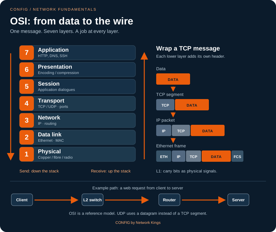
The seven layers, from the bottom
- Layer 1, Physical
- Moves bits as signals: voltage on copper, light in fibre, radio waves in Wi-Fi. Defines connectors (RJ-45, LC), cable types, pin-outs, speeds and signal encoding. Devices that work only here: hubs, repeaters, media converters, the cable itself. A hub has no idea what a MAC address is; it repeats every bit out of every port.
- Layer 2, Data link
- Delivers frames between devices on the same link or LAN. Uses MAC addresses (48-bit physical addresses), detects corrupted frames with the FCS, and controls access to the medium. Ethernet (IEEE 802.3) and Wi-Fi (802.11) are Layer 2 standards. Devices: switches (bridges), wireless access points, NICs. IEEE splits this layer into LLC (upper) and MAC (lower) sublayers.
- Layer 3, Network
- Delivers packets end to end across many networks. Uses logical addresses (IPv4, IPv6), and chooses a path (routing). Devices: routers, Layer 3 switches, and firewalls acting as routers. Protocols: IP, ICMP, and routing protocols such as OSPF.
- Layer 4, Transport
- Delivers data process to process using port numbers, so the right application on the host receives it. TCP adds reliability (sequencing, acknowledgements, retransmission, flow control); UDP adds only ports and a checksum. PDU: segment for TCP, datagram for UDP. Stateful firewalls track Layer 4 sessions.
- Layer 5, Session
- Opens, manages and closes dialogues between applications (for example, keeping a remote-desktop or database session in step). In TCP/IP, this job lives inside the applications themselves.
- Layer 6, Presentation
- Formats the data so both sides understand it: character encoding (ASCII, UTF-8), compression, and encryption. TLS is often described as working here, although in practice it sits between TCP and the application.
- Layer 7, Application
- The network services an application uses: HTTP, DNS, SMTP, SSH, DHCP, SNMP. Note: this is the protocol, not the program. Chrome is not Layer 7; the HTTP it speaks is.
Two ways layers interact
Same-layer interaction happens between the same layer on two devices: PC1's TCP talks to SRV's TCP using the TCP header (SYN, ACK, sequence numbers). Adjacent-layer interaction happens inside one device: TCP hands its segment down to IP and asks "deliver this to 203.0.113.80"; IP asks Ethernet "deliver this to the gateway's MAC". Each layer's header is a message to its twin on the other side.
Memory aids
Top down: "All People Seem To Need Data Processing". Bottom up: "Please Do Not Throw Sausage Pizza Away". For PDUs from Layer 4 down: "Some People Fear Birthdays" (segment, packet, frame, bits).
| Layer | PDU | Address used | Typical device |
|---|---|---|---|
| 7-5 Application, Presentation, Session | Data | Names, URLs | Servers, proxies, NGFW app inspection |
| 4 Transport | Segment / datagram | Port numbers | Stateful firewall, load balancer |
| 3 Network | Packet | IP address | Router, L3 switch |
| 2 Data link | Frame | MAC address | Switch, access point, NIC |
| 1 Physical | Bits | None | Hub, repeater, cable |
Worked example. In Lab 1, PC1's web request is described in OSI terms like this. L7: "GET / HTTP/1.1". L4: TCP, source port 49875 (random), destination port 80. L3: IPv4 from 10.1.1.10 to 203.0.113.80, TTL 64, Protocol 6. L2: Ethernet from PC1's MAC to R1 Gi0/0's MAC, EtherType 0x0800. L1: electrical signals on the cable to SW1 Gi0/1. SW1 reads up to L2 only; R1 reads up to L3; SRV reads all the way to L7.
Why the OSI model still matters
Nobody runs "OSI protocols" today, but the layer numbers are the shared language of the industry. Vendors sell "Layer 3 switches" and "Layer 7 load balancers", and tickets say "Layer 1 issue on the uplink". A troubleshooting method (bottom-up, top-down, or divide-and-conquer starting at Layer 3 with a ping) only works if you know what lives at each layer.
Common mistakes. Saying a switch is "Layer 3" because it has an IP address for management: a plain switch still forwards user frames by MAC only. Calling the browser the application layer. Putting ARP firmly in one layer in an argument: ARP maps Layer 3 to Layer 2 addresses and is usually described as Layer 2 (its frames have no IP header), sometimes as "Layer 2.5".
Exam traps. The PDU at Layer 3 is a packet, at Layer 2 a frame; do not swap them. Encryption and compression are Presentation (L6). Port numbers are Layer 4, not Layer 3. A hub is Layer 1, a bridge or switch Layer 2, a router Layer 3.
The "Layer 3 problem" that was a cable
A branch router's WAN interface showed "down/down" and the branch team insisted routing was broken because OSPF had lost its neighbour. The engineer ran show interfaces and saw line protocol down with the interface itself down and input errors climbing before it failed. Layer 1 was the problem: a damaged fibre patch cable. Replacing the patch lead restored the link, and OSPF came back on its own.
Lesson: higher layers depend on lower ones. Before debugging a routing protocol, prove Layers 1 and 2 are healthy.
"Walk me through the OSI model and give a device and a protocol at each layer."
Go bottom up and be concrete: L1 bits, cable, hub; L2 frames, MAC, Ethernet, switch; L3 packets, IP, router; L4 segments, TCP/UDP ports, stateful firewall; L5 sessions; L6 encoding and encryption; L7 HTTP, DNS, SSH. Finish with why it matters: "I use it to troubleshoot bottom up." Mentioning PDUs and same-layer versus adjacent-layer interaction shows depth.
Key takeaways
- OSI has seven layers: Physical, Data link, Network, Transport, Session, Presentation, Application.
- PDUs: bits (L1), frame (L2), packet (L3), segment or datagram (L4), data (L5-7).
- Hub = L1, switch = L2 (MAC), router = L3 (IP), stateful firewall = L4, NGFW inspects up to L7.
- Same-layer interaction is between devices; adjacent-layer interaction is inside one device.
- The layer numbers are the industry's troubleshooting language.
The TCP/IP model and how it maps to OSI
If the OSI model is the textbook description of how a restaurant should run, the TCP/IP model is the kitchen that actually serves food every night. It grew out of the US research network ARPANET in the 1970s and 1980s, it is defined in open documents called RFCs (Requests for Comments), and it is what every phone, laptop, router and cloud server runs today. The OSI model gave us vocabulary; TCP/IP gave us working protocols.
The layers of the TCP/IP model
The original standard for hosts (RFC 1122) describes four layers. Many textbooks, including Cisco's CCNA material, use an updated five-layer version that splits the bottom layer into data link and physical, so it lines up neatly with OSI.
| TCP/IP (4-layer) | TCP/IP (5-layer) | OSI layers | Example protocols |
|---|---|---|---|
| Application | Application | 7, 6, 5 | HTTP, HTTPS, DNS, DHCP, SSH, SMTP, SNMP, NTP |
| Transport | Transport | 4 | TCP, UDP |
| Internet | Network | 3 | IPv4, IPv6, ICMP, OSPF |
| Link (Network access) | Data link | 2 | Ethernet, 802.11 Wi-Fi, PPP, ARP |
| Physical | 1 | Copper, fibre, radio |
How deep each device reads. Only the two end hosts look at TCP and HTTP.
What each TCP/IP layer does
- Application layer. Everything the user's software needs from the network: fetching web pages (HTTP, HTTPS), resolving names (DNS), getting an address (DHCP), remote login (SSH), email (SMTP), monitoring (SNMP), time (NTP). OSI's session and presentation jobs are done inside these protocols; for example TLS handles encryption for HTTPS.
- Transport layer. Picks the application with port numbers. TCP is connection-oriented and reliable; UDP is connectionless and light. Chapter 8 goes deep.
- Internet layer. IP gives every host a logical address and routers forward packets hop by hop toward the destination network. ICMP (ping, traceroute, unreachable messages) is a helper at this layer.
- Link layer. Moves the packet across one physical network: Ethernet framing and MAC addresses, Wi-Fi, and the physical signalling underneath.
Why TCP/IP won
TCP/IP was running and free while OSI protocols were still being written by committees. Its standards were open RFCs, it came built into UNIX, and the internet grew on it. OSI survives as a teaching and troubleshooting reference; the OSI layer numbers stuck because they are more precise than TCP/IP's four names.
Devices do not always fit one layer
Real products blur the lines. A Layer 3 switch forwards frames by MAC inside a VLAN and routes packets by IP between VLANs, in hardware. A router can run a firewall, NAT (which rewrites Layer 3 and Layer 4 fields) and even DHCP (an application). A next-generation firewall inspects everything up to the application. When an exam asks "at which layer does X operate", answer with its primary forwarding decision: switch = L2 (MAC), router = L3 (IP).
Worked example. Map the Lab 1 conversation to TCP/IP. Application: HTTP "GET /" from PC1 and "HTTP/1.1 200 OK" from SRV. Transport: TCP, PC1 port 49875 to SRV port 80. Internet: IPv4 10.1.1.10 to 203.0.113.80, TTL 64 leaving PC1 and 63 after R1. Link: Ethernet II, first from PC1's MAC to R1 Gi0/0's MAC, then from R1 Gi0/1's MAC to SRV's MAC. Four layers, four headers, one click.
Checking the layers from the CLI
You can test each layer with a command you already know from ccna-ios:
! Link layer: is the interface up and which MAC does it own?
R1# show interfaces GigabitEthernet0/0
! Internet layer: can I reach the far end?
R1# ping 203.0.113.80
! Mapping between the two: which MAC belongs to which IP?
R1# show ip arp
R1# show interfaces GigabitEthernet0/0
GigabitEthernet0/0 is up, line protocol is up
  Hardware is iGbE, address is 5254.0c04.4b01 (bia 5254.0c04.4b01)
  Description: LAN
  Internet address is 10.1.1.1/24
  MTU 1500 bytes, BW 1000000 Kbit/sec, DLY 10 usec,
"Interface is up" is Layer 1 (a signal); "line protocol is up" is Layer 2 (framing works). Both must be up before any Layer 3 test can succeed.
Common mistakes. Saying TCP/IP has "seven layers". Forgetting that the TCP/IP application layer covers OSI 5, 6 and 7. Believing a router reads TCP ports to forward normal traffic: routing uses only the destination IP (ports matter only if you add ACLs, NAT or policy features).
Exam traps. TCP/IP's layer 3 is called Internet, not "Network", in the 4-layer version. The bottom layer is called Link or Network access. If a question says "TCP/IP model" and lists "Session" as an option, that option is wrong.
The firewall that "broke" DNS
After a new firewall rule set was pushed, users could browse by IP but not by name. The rule allowed "DNS" as TCP port 53 only. Normal DNS queries use UDP 53 (TCP 53 is used for large replies and zone transfers). The engineer checked the transport layer in a capture, saw UDP 53 queries leaving and no replies returning, and added UDP 53. Names resolved immediately.
Lesson: knowing which transport a protocol uses is not trivia; it decides whether your rules work.
"Compare the OSI and TCP/IP models. Which one do we actually use?"
Say that TCP/IP is the protocol suite the internet runs, with four layers (application, transport, internet, link), and OSI is a seven-layer reference used as vocabulary. Map them: TCP/IP application = OSI 5-7, link = OSI 1-2. Add that engineers use OSI numbers in conversation ("L2 issue", "L7 firewall") but configure TCP/IP protocols.
Key takeaways
- TCP/IP layers: Application, Transport, Internet, Link (5-layer version splits Link into Data link and Physical).
- TCP/IP application = OSI 5, 6 and 7; TCP/IP link = OSI 1 and 2.
- End hosts process every layer; routers stop at Internet; switches stop at Link.
- Answer "which layer" questions with the device's primary forwarding decision.
- "Interface up" is Layer 1; "line protocol up" is Layer 2.
Encapsulation and decapsulation
Think of a gift inside a box, inside a padded envelope, inside a courier bag. Whoever packs it adds one layer at a time, starting from the gift. Whoever receives it removes one layer at a time, starting from the outside, and each wrapper has a label that tells you what is inside the next one. That packing is encapsulation; the unpacking is decapsulation (also called de-encapsulation).
Encapsulation on the sender, step by step
Follow PC1 as it sends "GET /" to SRV in Lab 1:
- Application. The web client creates the request text:
GET / HTTP/1.1,Host: 203.0.113.80. This is the data. - Transport. TCP adds a header of at least 20 bytes: source port (a random high port such as 49875), destination port 80, sequence and acknowledgement numbers, flags, window. Data plus TCP header = a segment.
- Internet. IP adds a 20-byte header: source 10.1.1.10, destination 203.0.113.80, TTL 64, and Protocol = 6 to say "a TCP segment is inside". Segment plus IP header = a packet.
- Link. Ethernet adds a 14-byte header (destination MAC, source MAC, EtherType 0x0800 meaning "IPv4 inside") and a 4-byte trailer, the FCS. Packet plus header and trailer = a frame.
- Physical. The NIC sends the frame as bits, preceded by a preamble so the receiver can lock on to the signal.
Each layer treats everything from above as its payload and adds its own header (and, for Ethernet, a trailer).
The chain of "what is inside" fields
A receiver only knows how to read the next header because the current header tells it. This chain is worth memorising:
| Header | Field | Common values |
|---|---|---|
| Ethernet | EtherType | 0x0800 IPv4, 0x0806 ARP, 0x86DD IPv6, 0x8100 802.1Q tag |
| IPv4 | Protocol (IPv6: Next Header) | 1 ICMP, 6 TCP, 17 UDP, 47 GRE, 50 ESP, 89 OSPF |
| TCP / UDP | Destination port | 22 SSH, 53 DNS, 80 HTTP, 443 HTTPS |
Decapsulation on the receiver
- SRV's NIC receives the bits, checks the FCS (a corrupted frame is silently dropped) and checks that the destination MAC is its own, a broadcast, or a multicast it has joined.
- It reads EtherType 0x0800 and hands the payload to IPv4.
- IPv4 checks the header checksum and that the destination IP 203.0.113.80 is its own, then reads Protocol 6 and hands the payload to TCP.
- TCP checks its checksum, finds the connection by the four values source IP, source port, destination IP, destination port, and delivers the data to the process listening on port 80.
- The web server reads "GET /" and builds a reply, which is encapsulated the same way in the other direction.
Worked example: overhead in numbers. Ethernet's standard MTU (maximum transmission unit, the largest packet the link carries) is 1500 bytes. Take away 20 bytes of IPv4 header and 20 bytes of TCP header and 1460 bytes remain for data; that is the typical TCP MSS (maximum segment size) announced in the SYN. The frame is 14 + 1500 + 4 = 1518 bytes. On the wire, 8 bytes of preamble and SFD and a 12-byte inter-frame gap are also spent, so 1460 useful bytes cost 1538 byte-times: about 95% efficiency.
What a capture shows
A packet analyser displays the layers exactly in encapsulation order, one line per header. Here is PC1's SYN from Lab 1:
Frame 4: 74 bytes on wire (592 bits), 74 bytes captured (592 bits)
Ethernet II, Src: 52:54:00:a1:00:10, Dst: 52:54:0c:04:4b:01
    Type: IPv4 (0x0800)
Internet Protocol Version 4, Src: 10.1.1.10, Dst: 203.0.113.80
    Time to Live: 64
    Protocol: TCP (6)
Transmission Control Protocol, Src Port: 49875, Dst Port: 80, Seq: 0, Len: 0
74 bytes = 14 (Ethernet) + 20 (IPv4) + 40 (TCP header with options such as MSS; no data yet). The analyser does not show the FCS by default because most NICs strip it before the capture software sees the frame.
Common mistakes. Thinking the FCS is part of the IP packet (it belongs to the Ethernet frame). Thinking a router keeps the original frame: it throws the Ethernet header and FCS away and builds a new frame for the next link (chapter 7). Forgetting that tunnels and VPNs add more headers, so the inner packet must be smaller than 1500 bytes.
Exam traps. Order of encapsulation: data, segment, packet, frame, bits. Only Layer 2 adds a trailer. "Which field identifies the Layer 4 protocol?" is the IP Protocol field, not the port.
Web pages hang over the new VPN
After a branch moved to an IPsec VPN, small pages loaded but large pages and file downloads hung. Ping with small packets worked. The engineer realised the tunnel adds its own headers (ESP and a new IP header, around 50 to 70 bytes), so full 1500-byte packets from the branch no longer fitted the 1500-byte internet link, and the servers' "fragmentation needed" ICMP messages were blocked on the way back. The fix was to clamp TCP MSS on the branch LAN interface so hosts send smaller segments: ip tcp adjust-mss 1360.
Lesson: every extra layer of encapsulation costs bytes. When "small works, big hangs", suspect MTU and overhead.
"Explain encapsulation using a web request."
Walk down the stack: HTTP data, TCP adds ports and sequence numbers (segment), IP adds source and destination IP, TTL and Protocol 6 (packet), Ethernet adds MACs, EtherType 0x0800 and FCS (frame), then bits. Then reverse it for decapsulation and mention the type-field chain. Strong candidates add the MTU/MSS arithmetic: 1500 minus 40 = 1460.
Key takeaways
- Encapsulation: data, then segment (TCP header), packet (IP header), frame (Ethernet header and FCS), bits.
- Decapsulation reverses it, checking FCS, MAC, IP and port at each step.
- Type fields chain the layers: EtherType, then IP Protocol, then port.
- MTU 1500, MSS 1460, Ethernet frame up to 1518 bytes (1522 with an 802.1Q tag).
- Tunnels add headers; "small works, big hangs" means MTU trouble.
The Ethernet frame and MAC addresses
Inside a large office, the internal mail trolley does not care about city names or postcodes. It needs just two things written on the envelope: which desk it goes to and which desk it came from. If the envelope is torn, the mail room throws it away. That internal envelope is the Ethernet frame, and the desk numbers are MAC addresses. Ethernet (IEEE 802.3) is the Layer 2 technology of almost every wired LAN and data center.
The Ethernet II frame, field by field
Sizes in bytes. The preamble and SFD are sent on the wire but are not counted in the frame size.
- Preamble (7 bytes) and SFD (1 byte)
- Alternating 1s and 0s (10101010) let the receiver synchronise its clock; the Start Frame Delimiter (10101011) says "the frame starts now". Captures do not show them.
- Destination MAC (6 bytes)
- Who on this link should receive the frame. It comes first so a switch can start its forwarding decision as soon as it has read six bytes.
- Source MAC (6 bytes)
- Who sent it on this link. Switches learn from this field: "MAC X lives behind port Gi0/1".
- Type / Length (2 bytes)
- In Ethernet II, the EtherType names the payload: 0x0800 IPv4, 0x0806 ARP, 0x86DD IPv6. Values of 1536 (0x0600) or more are types; values up to 1500 mean the older IEEE 802.3 length format, where an LLC header follows (used by, for example, spanning tree BPDUs).
- Payload (46 to 1500 bytes)
- The IP packet. If it is shorter than 46 bytes, padding is added so the frame reaches the minimum 64 bytes. The 1500-byte maximum is the Ethernet MTU.
- FCS (4 bytes)
- Frame Check Sequence, a CRC-32 computed over the frame. The receiver recalculates it; a mismatch means the frame was damaged, and it is discarded and counted as a CRC error. Ethernet detects errors but never corrects or resends; that is TCP's job.
MAC addresses
A MAC address is 48 bits, written as 12 hexadecimal digits. Cisco writes 5254.00a1.0010, most other systems write 52:54:00:a1:00:10 or 52-54-00-A1-00-10; all three are the same address. The first 24 bits are the OUI (Organisationally Unique Identifier) that the IEEE assigns to a manufacturer; the last 24 bits are chosen by the manufacturer. The address burned into the NIC is the BIA (burned-in address).
- Unicast: one NIC. The lowest bit of the first byte (the I/G bit) is 0.
- Multicast: a group. The I/G bit is 1. IPv4 multicast maps to MACs starting
0100.5e. - Broadcast: everyone on the LAN,
ffff.ffff.ffff. ARP requests use it.
Worked example. PC1's MAC is 52:54:00:a1:00:10. The first byte 0x52 is 0101 0010 in binary. The lowest bit is 0, so it is unicast. The next bit (the U/L bit) is 1, so it is a locally administered address, which is typical for virtual machines; 52:54:00 is the prefix commonly used by KVM/QEMU virtual NICs. A laptop's real NIC would have that bit set to 0 and a vendor OUI.
How SW1 uses the frame
SW1 checks the FCS, learns the source MAC against the incoming port, then looks up the destination MAC. Known unicast is sent out of one port; broadcast, multicast and unknown unicast are flooded out of every port in the VLAN except the one it came in on. SW1 changes nothing in the frame.
! Which MACs has SW1 learned, and on which ports?
SW1# show mac address-table dynamic
          Mac Address Table
-------------------------------------------

Vlan    Mac Address       Type        Ports
----    -----------       --------    -----
   1    5254.00a1.0010    DYNAMIC     Gi0/1
   1    5254.0c04.4b01    DYNAMIC     Gi0/0
Total Mac Addresses for this criterion: 2
PC1 lives behind Gi0/1 and R1's LAN interface behind Gi0/0, exactly as cabled. Notice there is no entry for SRV: SRV is on another subnet, and its frames never reach SW1.
A look ahead: the 802.1Q tag
On trunk links a switch inserts a 4-byte 802.1Q tag between the source MAC and the EtherType: TPID 0x8100, then 3 bits of priority (PCP), 1 DEI bit and a 12-bit VLAN ID. The maximum frame grows to 1522 bytes. You will configure this in ccna-vlans.
Common mistakes. Thinking the switch "adds its own MAC" to frames it forwards (it does not). Mixing up MTU (1500, the payload) and frame size (1518). Assuming a CRC error was caused by the device that reports it: the counter increments on the receiving side, so the bad cable, optic or far-end port is on that link.
Exam traps. Ethernet header = 14 bytes, FCS = 4 bytes, minimum frame = 64 bytes, maximum = 1518 (1522 tagged). The FCS detects errors only. The EtherType for IPv4 is 0x0800 and for ARP 0x0806. The OUI is the first half of the MAC.
The printer that dropped jobs
Users complained that large print jobs to one floor printer failed randomly. On the access switch the engineer ran show interfaces GigabitEthernet1/0/14 and saw input errors and CRC counters increasing every few seconds while other ports were clean. The FCS check was failing on frames arriving from the printer, so the switch discarded them and TCP kept retransmitting until the job timed out. A crushed patch cable under a desk leg was replaced; the counters stopped and print jobs finished.
Lesson: CRC and FCS errors point to the physical path of that link. Clear the counters, watch them, and fix the cable or optic before touching configuration.
"What is in an Ethernet header and what does a switch do with it?"
Name the fields in order: destination MAC, source MAC, EtherType (plus preamble/SFD before and FCS after). Explain that the switch learns the source MAC, forwards or floods based on the destination MAC, drops frames that fail the FCS, and changes nothing. Bonus: explain why destination comes first (cut-through switching) and what the 802.1Q tag adds.
Key takeaways
- Ethernet II: Preamble+SFD, destination MAC, source MAC, EtherType, payload 46-1500, FCS.
- Frame size 64 to 1518 bytes; MTU 1500; 802.1Q adds 4 bytes.
- MAC = 48 bits: 24-bit OUI + 24-bit vendor part; unicast, multicast, broadcast ffff.ffff.ffff.
- Switches learn source MACs, forward on destination MAC, flood unknown and broadcast, and never modify the frame.
- FCS failures mean discarded frames and a physical problem on that link.
The IPv4 header, field by field
If the Ethernet frame is the office's internal envelope, the IPv4 header is the courier waybill glued to the parcel. It holds the full sender and receiver addresses, a "handle with care" class, a note of what kind of item is inside, and a "return to sender after N hubs" counter so a parcel that gets lost in a loop does not travel forever. Every router reads this waybill, and only a few boxes on it are ever changed on the way.
The layout: 20 bytes in five 32-bit rows
The fixed 20-byte IPv4 header. Options, rarely used, can extend it up to 60 bytes.
Every field explained
- Version (4 bits)
- 4 for IPv4. IPv6 has its own, different header with value 6.
- IHL, Internet Header Length (4 bits)
- Header length in 32-bit words. The minimum 5 means 20 bytes; the maximum 15 means 60 bytes (with options).
- DSCP and ECN (8 bits, formerly Type of Service)
- 6 bits of DSCP mark the packet's QoS class (for example EF, value 46, for voice), and 2 bits of ECN signal congestion without dropping.
- Total Length (16 bits)
- Header plus data in bytes, so at most 65,535. On Ethernet it is normally at most 1500.
- Identification, Flags, Fragment Offset
- Used for fragmentation. If a packet is bigger than the next link's MTU, a router may split it; every fragment carries the same Identification, the MF (more fragments) flag, and an offset in 8-byte units. The DF (don't fragment) flag forbids splitting; the router then drops the packet and sends ICMP "fragmentation needed" back, which is how path MTU discovery works. Most modern hosts set DF.
- TTL, Time to Live (8 bits)
- A hop counter. The sender sets it (Linux, macOS and our lab PCs use 64, Windows 128, Cisco IOS 255). Every router subtracts 1; a router that reduces it to 0 discards the packet and sends ICMP Time Exceeded (type 11) to the source. This kills packets caught in routing loops, and traceroute uses it deliberately.
- Protocol (8 bits)
- What is inside: 1 ICMP, 2 IGMP, 6 TCP, 17 UDP, 47 GRE, 50 ESP, 51 AH, 88 EIGRP, 89 OSPF, 112 VRRP.
- Header Checksum (16 bits)
- Protects the header only, not the data. Because TTL changes at every hop, every router must recalculate it.
- Source and Destination address (32 bits each)
- The end-to-end addresses. Routers forward on the destination; without NAT neither changes along the path.
Reading the header in a capture
Here is PC1's SYN from Lab 1, captured on the PC1-SW1 link, with the IPv4 layer expanded:
Internet Protocol Version 4, Src: 10.1.1.10, Dst: 203.0.113.80
    0100 .... = Version: 4
    .... 0101 = Header Length: 20 bytes (5)
    Differentiated Services Field: 0x00 (DSCP: CS0, ECN: Not-ECT)
    Total Length: 60
    Identification: 0x1c46 (7238)
    010. .... = Flags: 0x2, Don't fragment
    ...0 0000 0000 0000 = Fragment Offset: 0
    Time to Live: 64
    Protocol: TCP (6)
    Header Checksum: 0x9d2a [validation disabled]
    Source Address: 10.1.1.10
    Destination Address: 203.0.113.80
Worked example. Total Length 60 = 20 bytes of IPv4 header + 40 bytes of TCP header (the SYN carries options and no data). The same packet captured on the R1-SRV link shows Time to Live: 63 and a different Header Checksum, while source, destination, Identification, Protocol and Total Length are identical. The server's reply leaves with TTL 64 and arrives at PC1 with 63, which is why ping 203.0.113.80 from PC1 shows ttl=63. From the TTL you can even guess the far end's OS and distance: a reply arriving with 117 probably started at 128 (Windows) and crossed 11 routers.
ICMP: IP's messenger
ICMP (Protocol 1) carries control messages about IP. You will meet: Echo Request (type 8) and Echo Reply (type 0) used by ping; Destination Unreachable (type 3), with codes such as 1 host unreachable, 3 port unreachable, 4 fragmentation needed, 13 administratively prohibited; and Time Exceeded (type 11) used by traceroute. Traceroute sends probes with TTL 1, 2, 3 and so on; each router that drops a probe at TTL 0 reveals itself with a Time Exceeded message.
Common mistakes. Thinking the IP checksum protects the data (TCP and UDP have their own checksums). Believing TTL is measured in seconds (historically intended, in practice a hop count). Blocking all ICMP on a firewall "for security": it breaks path MTU discovery and hides useful errors. Permit at least unreachables and Time Exceeded.
Exam traps. Minimum IPv4 header = 20 bytes. Protocol 6 = TCP, 17 = UDP, 1 = ICMP, 89 = OSPF. Fields a router changes on every hop: TTL and Header Checksum (plus fragmentation fields only if it fragments, and addresses only with NAT). DSCP is the QoS marking in the old ToS byte.
The loop that traceroute revealed
A new remote subnet 198.51.100.0/24 was unreachable. traceroute from the core showed hop 1 as the edge router, hop 2 as the core, hop 3 as the edge again, alternating until 30 hops. Each router had a static route pointing at the other for that prefix, so packets bounced until TTL reached 0 and ICMP Time Exceeded came back. The engineer corrected the edge router's static route to point at the WAN next hop, and the trace completed in three hops.
Lesson: TTL is the internet's safety fuse. When a trace alternates between two routers, you have a routing loop, and TTL expiry is what stopped it from melting the link.
"Which fields of the IPv4 header change as a packet crosses a router, and why?"
Answer: TTL decreases by one to stop loops, so the header checksum must be recalculated. Source and destination IP stay the same unless NAT is used; the Ethernet header is completely rebuilt (that is Layer 2, not IP). Mention fragmentation fields change only if the router fragments, which is rare because hosts set DF and use path MTU discovery.
Key takeaways
- IPv4 header: 20 bytes minimum; Version, IHL, DSCP/ECN, Total Length, ID/Flags/Offset, TTL, Protocol, Checksum, Source, Destination.
- TTL drops by 1 per router; at 0 the packet dies and ICMP Time Exceeded goes back.
- Protocol field: 1 ICMP, 6 TCP, 17 UDP, 89 OSPF.
- Header checksum covers only the header and is recalculated at every hop.
- DF plus ICMP "fragmentation needed" = path MTU discovery; do not block all ICMP.
What changes hop by hop: switch, router, ARP and TTL
Back to the courier. Your parcel's waybill says "Delhi to Bengaluru" for the whole trip. But the first truck only goes from your house to the Delhi hub; its driver needs the hub's gate number, not Bengaluru. At the hub the parcel is unloaded, the waybill is read, a counter is stamped, and it goes onto a new truck with a new driver to the next hub. This chapter is that story with real addresses, and it is exactly what Lab 1 asks you to prove from the capture.
Step 1: PC1 decides where to send the frame
PC1 (10.1.1.10/24) wants to reach 203.0.113.80. It compares the destination with its own subnet. 203.0.113.80 is not inside 10.1.1.0/24, so PC1 must send the packet to its default gateway, 10.1.1.1. The IP destination stays 203.0.113.80; only the Layer 2 destination becomes the gateway. If the destination were local (say 10.1.1.20), PC1 would send straight to that host's MAC instead.
Step 2: ARP finds the gateway's MAC
PC1 knows the gateway's IP but not its MAC, so it uses ARP (Address Resolution Protocol, EtherType 0x0806). The request is a broadcast to ffff.ffff.ffff: "Who has 10.1.1.1? Tell 10.1.1.10". Every device in the VLAN receives it; only R1 answers with a unicast reply: "10.1.1.1 is at 52:54:0c:04:4b:01". PC1 caches it in its ARP table (our lab PCs keep entries for 120 seconds; Cisco routers keep them for 4 hours by default).
No. Source              Destination         Protocol Info
1   52:54:00:a1:00:10   ff:ff:ff:ff:ff:ff   ARP      Who has 10.1.1.1? Tell 10.1.1.10
2   52:54:0c:04:4b:01   52:54:00:a1:00:10   ARP      10.1.1.1 is at 52:54:0c:04:4b:01
3   10.1.1.10           203.0.113.80        TCP      49875 → 80 [SYN] Seq=0 Win=64240 Len=0 MSS=1460
Step 3: SW1 forwards the frame unchanged
SW1 learns PC1's MAC on Gi0/1, looks up the destination MAC 5254.0c04.4b01, finds it on Gi0/0, and sends the frame out unchanged. MACs, IPs, TTL, checksum: nothing is touched. A switch is transparent.
Step 4: R1 routes and rewrites
- R1 receives the frame on Gi0/0, checks the FCS and that the destination MAC is its own.
- It strips the Ethernet header and trailer (they have done their job).
- It looks up 203.0.113.80 in the routing table and finds the connected route 203.0.113.0/24 out of Gi0/1.
- It decrements TTL from 64 to 63 (if it reached 0 it would drop the packet and send ICMP Time Exceeded) and recalculates the header checksum.
- It ARPs on Gi0/1 for 203.0.113.80 if the MAC is not already cached.
- It builds a new frame: source MAC = R1 Gi0/1, destination MAC = SRV, EtherType 0x0800, new FCS.
The same SYN seen on the three links of the lab.
Proving it on R1
! Lab 1 task: the destination MAC of PC1's SYN = R1 Gi0/0's MAC
R1# show interfaces GigabitEthernet0/0 | include address
! Lab 1 task: R1 needs a MAC on each segment it forwards between
R1# show ip arp
R1# show ip route
R1# show interfaces GigabitEthernet0/0 | include address
  Hardware is iGbE, address is 5254.0c04.4b01 (bia 5254.0c04.4b01)
  Internet address is 10.1.1.1/24
R1# show ip arp
Protocol  Address          Age (min)  Hardware Addr   Type   Interface
Internet  10.1.1.1                -   5254.0c04.4b01  ARPA   GigabitEthernet0/0
Internet  10.1.1.10               0   5254.00a1.0010  ARPA   GigabitEthernet0/0
Internet  203.0.113.1             -   5254.0c04.4b02  ARPA   GigabitEthernet0/1
Internet  203.0.113.80            0   5254.00c3.0080  ARPA   GigabitEthernet0/1
R1# show ip route | begin Gateway
Gateway of last resort is not set

      10.0.0.0/8 is variably subnetted, 2 subnets, 2 masks
C        10.1.1.0/24 is directly connected, GigabitEthernet0/0
L        10.1.1.1/32 is directly connected, GigabitEthernet0/0
      203.0.113.0/24 is variably subnetted, 2 subnets, 2 masks
C        203.0.113.0/24 is directly connected, GigabitEthernet0/1
L        203.0.113.1/32 is directly connected, GigabitEthernet0/1
Entries with age "-" are R1's own interfaces. The MAC values in your lab may differ; compare the capture with your own show output.
Worked example: the Lab 1 answers. Destination MAC of the SYN on the PC1-SW1 link = R1 Gi0/0's MAC (5254.0c04.4b01 here), not SRV's. TTL on the R1-SRV link = 64 - 1 router = 63. The IP Protocol field = 6 (TCP). R1's ARP table holds 10.1.1.10 and 203.0.113.80. On the way back everything mirrors: SRV sends to R1 Gi0/1's MAC with TTL 64, R1 rewrites the frame to PC1's MAC and TTL 63.
The exception: NAT
If a router performs NAT (for example, a home router translating 192.168.1.10 to its public address), it also rewrites the source IP and usually the source port. That is a deliberate extra feature, covered in ccna-nat. Without NAT, IP addresses and ports are end to end.
Common mistakes. Answering "the server's MAC" for a remote destination. Believing the switch adds its MAC. Forgetting ARP happens per segment: PC1 never learns SRV's MAC and does not need to. Configuring a wrong default gateway on a host: it can reach local hosts but nothing remote.
Exam traps. Per router hop: source and destination MAC change, TTL decrements, IP checksum and FCS are recalculated; source and destination IP stay the same (without NAT). ARP request = broadcast, ARP reply = unicast. A switch forwards frames without changing them.
Only one user cannot leave the subnet
A user could print to a local printer and reach a colleague's PC, but no server in the data center. Her ARP table (arp -a) showed an entry for 10.1.1.254 and no entry for the real gateway 10.1.1.1. Someone had typed the wrong default gateway on her static configuration, so every off-subnet packet was framed to a MAC that did not route. Correcting the gateway to 10.1.1.1 fixed it instantly.
Lesson: local traffic depends only on ARP for the target; remote traffic depends on the default gateway. "Local works, remote fails" on one host means check the gateway first.
"A PC sends a packet to a server in another subnet. Describe the addresses on each link."
Say: the PC sees the destination is remote, ARPs for its default gateway, and sends a frame with its own MAC as source and the gateway's MAC as destination, while the IP header carries PC to server. The switch forwards unchanged. The router strips the frame, routes on the destination IP, decrements TTL, recomputes the checksum, and builds a new frame from its egress MAC to the next hop's MAC. IPs stay the same unless NAT. Draw it if there is a whiteboard.
Key takeaways
- Remote destination: the frame goes to the default gateway's MAC; the IP destination stays the final host.
- ARP resolves IP to MAC on each segment: request broadcast, reply unicast.
- Switches change nothing; routers rebuild the Ethernet header, decrement TTL and recompute the checksum.
- IP addresses and ports stay end to end unless NAT/PAT is configured.
show ip arp,show ip routeandshow interfacesprove each step on R1.
TCP vs UDP: handshake, sequence numbers, windowing and ports
Two ways to send documents. A registered courier: you phone first to check someone is in, every page is numbered, the receiver signs for what arrived, missing pages are sent again, and at the end both sides agree the delivery is complete. A flyer drop: you push paper through the letterbox and walk on; fast and cheap, no guarantee. TCP is the registered courier. UDP is the flyer drop. Both live at Layer 4 and both use port numbers to hand data to the right application.
Ports and sockets
A port is a 16-bit number (0-65535) that identifies an application on a host. Servers listen on well-known ports (0-1023) or registered ports (1024-49151). Clients pick a random ephemeral source port (IANA range 49152-65535; Linux uses 32768-60999 by default). A connection is identified by the socket pair: source IP, source port, destination IP, destination port (plus the protocol). That is how one PC can open ten browser tabs to the same server: each uses a different source port.
| Port | Protocol | Transport | Port | Protocol | Transport |
|---|---|---|---|---|---|
| 20, 21 | FTP data, control | TCP | 67, 68 | DHCP server, client | UDP |
| 22 | SSH, SCP, SFTP | TCP | 69 | TFTP | UDP |
| 23 | Telnet | TCP | 123 | NTP | UDP |
| 25 | SMTP | TCP | 161, 162 | SNMP, SNMP traps | UDP |
| 53 | DNS | UDP (TCP for large replies) | 514 | Syslog | UDP |
| 80 | HTTP | TCP | 110 / 143 | POP3 / IMAP | TCP |
| 443 | HTTPS | TCP (UDP for HTTP/3) | 3389 | RDP | TCP |
The TCP header
At least 20 bytes: source port and destination port (16 bits each), sequence number (32 bits, the number of the first data byte in this segment), acknowledgement number (32 bits, the next byte expected from the other side), data offset (header length), flags (SYN, ACK, FIN, RST, PSH, URG, plus ECE and CWR), window (16 bits, how many bytes the sender of this segment can still receive), checksum (covers header and data) and urgent pointer. Options such as MSS, window scale and SACK appear in the SYN.
The three-way handshake
Relative sequence numbers, as a packet analyser shows them.
- SYN: the client picks an initial sequence number (random; analysers show it as relative 0) and offers options such as MSS 1460.
- SYN-ACK: the server picks its own initial sequence number and acknowledges the client's SYN with ack = client ISN + 1. A SYN consumes one sequence number.
- ACK: the client acknowledges the server's SYN. Both sides are now ESTABLISHED and data can flow.
Sequence and acknowledgement numbers
TCP numbers bytes, not segments. If PC1 sends 60 bytes starting at seq 1, SRV answers ack 61: "I have everything up to byte 60, send 61 next". Acknowledgements are cumulative. If a segment is lost, the receiver keeps acknowledging the last in-order byte; after a timeout (or three duplicate ACKs, called fast retransmit) the sender retransmits. The receiver uses sequence numbers to put segments back in order and discard duplicates.
Windowing and flow control
Waiting for an ACK after every segment would be very slow. Instead the receiver advertises a window: how many bytes may be in flight unacknowledged. The window slides forward as ACKs arrive. If the receiving application is slow, its buffer fills, the advertised window shrinks, and at window 0 the sender must pause. That is flow control: the receiver protects itself. The window-scale option lets windows exceed 64 KB on fast links. (Separately, the sender runs congestion control, such as slow start, to protect the network.)
Closing: four steps, or a reset
A graceful close uses FIN in each direction, each acknowledged: FIN, ACK, FIN, ACK (the middle two are often combined into one FIN-ACK segment). The side that closes first waits in TIME_WAIT for a while before reusing the socket. An RST aborts immediately; a server sends RST to a SYN for a port where nothing listens, which the client reports as "connection refused".
UDP
The UDP header is just 8 bytes: source port, destination port, length, checksum. No handshake, no sequence numbers, no acknowledgements, no retransmission, no windows. Applications that need speed or can tolerate loss use it: voice and video (a late packet is useless), DNS queries (one question, one answer, retry if needed), DHCP, TFTP, SNMP, syslog, NTP. If an application needs reliability over UDP, it builds its own (as TFTP and QUIC do).
| Feature | TCP | UDP |
|---|---|---|
| Connection | Connection-oriented (handshake) | Connectionless |
| Reliability | ACKs, retransmission, ordering | None (best effort) |
| Flow control | Sliding window | None |
| Header size | 20-60 bytes | 8 bytes |
| Typical uses | Web, SSH, email, file transfer | Voice, video, DNS, DHCP, SNMP, syslog |
Worked example: the Lab 1 conversation.
No. Source         Destination    Protocol Info
3   10.1.1.10      203.0.113.80   TCP   49875 → 80 [SYN] Seq=0 Win=64240 Len=0 MSS=1460
4   203.0.113.80   10.1.1.10      TCP   80 → 49875 [SYN, ACK] Seq=0 Ack=1 Win=65160 Len=0 MSS=1460
5   10.1.1.10      203.0.113.80   TCP   49875 → 80 [ACK] Seq=1 Ack=1 Win=64240 Len=0
6   10.1.1.10      203.0.113.80   HTTP  GET / HTTP/1.1
7   203.0.113.80   10.1.1.10      TCP   80 → 49875 [ACK] Seq=1 Ack=61 Win=65160 Len=0
8   203.0.113.80   10.1.1.10      HTTP  HTTP/1.1 200 OK  (text/html)
PC1's request is 60 bytes (seq 1 to 60), so SRV acknowledges 61. The destination port is 80; the source 49875 is ephemeral, and the reply simply swaps them. In Lab 2 you will be asked for exactly these: the SYN-ACK flags and the destination port.
Common mistakes. Saying UDP is "unreliable so bad": it is the right choice for real-time traffic. Thinking the ACK number is the number of the segment received (it is the next byte expected). Opening only TCP 53 for DNS on a firewall. Confusing flow control (receiver's window) with congestion control (sender's own limit).
Exam traps. Handshake order SYN, SYN-ACK, ACK; close uses FIN and ACK (four segments). TCP header 20 bytes minimum, UDP 8 bytes. DHCP 67/68, TFTP 69, SNMP 161/162, syslog 514 and NTP 123 are UDP; SSH 22, Telnet 23, SMTP 25, HTTP 80, HTTPS 443 are TCP; DNS uses both.
"The network is slow" that was the server
Users said file uploads to an internal application crawled. The network team captured on the server's switch port and filtered for the upload. The server repeatedly advertised Win=0 ("TCP ZeroWindow"), the clients paused, sent small window probes, then resumed a little. Links were at 3% utilisation with no drops. The application was writing uploads to a full disk and could not empty its receive buffer. After storage was expanded, windows stayed open and uploads ran at full speed.
Lesson: TCP flow control tells you who is slow. A zero window is the receiver saying "stop", which points at the host, not the network.
"Explain the TCP three-way handshake with sequence numbers, and when you would choose UDP."
Describe SYN (client ISN x), SYN-ACK (server ISN y, ack x+1), ACK (ack y+1), and that the SYN and FIN each consume one sequence number. Explain that ACK numbers are the next byte expected and that the window provides flow control. For UDP, give reasons: low latency, no connection setup, loss-tolerant or request-response apps like voice, DNS and DHCP. Senior candidates mention QUIC (HTTP/3) building reliability on top of UDP 443.
Key takeaways
- Ports pick the application; a socket pair (IPs, ports, protocol) identifies a connection; clients use ephemeral source ports.
- TCP: SYN, SYN-ACK, ACK; byte-numbered sequences; cumulative ACK = next byte expected; retransmission; FIN or RST to close.
- The advertised window gives flow control; window 0 means the receiver is full.
- UDP: 8-byte header, no handshake, no reliability; used for voice, video, DNS, DHCP, SNMP, syslog, NTP, TFTP.
- Know the well-known ports and whether each runs over TCP or UDP.
Network components and their roles
Picture a big corporate campus. There are security guards at the main gate, receptionists on every floor who direct visitors to the right desk, corridors and lifts that connect floors, a control room that manages all the Wi-Fi hotspots, the employees themselves, and the service rooms (canteen, mail room, records). Every network diagram you will see in your career has the same cast: firewalls, switches, routers, access points and controllers, endpoints and servers. The CCNA blueprint asks you to explain the role and function of each.
A small enterprise: every component the CCNA blueprint lists appears once.
Routers
A router connects different IP networks and forwards packets between them using its routing table (Layer 3). It separates broadcast domains: an ARP broadcast never crosses a router. Routers connect the LAN to the WAN and internet, choose best paths with routing protocols such as OSPF, and often provide edge services such as NAT, DHCP, VPN termination and QoS. R1 in our lab is a router between 10.1.1.0/24 and 203.0.113.0/24.
Layer 2 and Layer 3 switches
A Layer 2 switch connects devices in the same LAN, learns MAC addresses into its MAC address table, forwards frames by destination MAC, floods unknowns and broadcasts, and supports VLANs to split one switch into several broadcast domains. Each switch port is its own collision domain, and full duplex removes collisions entirely. A Layer 3 switch (multilayer switch) does all that and also routes between VLANs in hardware using SVIs (switched virtual interfaces) or routed ports. It is the usual distribution and core device in a campus because it routes at wire speed with many ports, while a router offers more WAN interfaces and edge features.
Next-generation firewalls and IPS
A firewall enforces a security policy between zones (inside, outside, DMZ). A classic stateful firewall tracks each connection (Layer 3 and 4) and automatically allows return traffic for sessions started from the inside. A next-generation firewall (NGFW) adds application visibility and control (it can permit "Webex" and block "BitTorrent" even on the same port), user identity, URL filtering, malware protection and an integrated IPS. An IPS (intrusion prevention system) sits inline and drops traffic that matches attack signatures or anomalies; an IDS only watches a copy of the traffic (from a SPAN port or tap) and alerts.
Access points and controllers
An access point (AP) bridges wireless clients (IEEE 802.11) onto the wired Ethernet network. An autonomous AP is configured one by one. In larger networks lightweight APs are managed centrally by a wireless LAN controller (WLC): they build CAPWAP tunnels to it (UDP 5246 for control, 5247 for data), and the WLC pushes SSIDs, security, radio channels and power, and handles roaming. More broadly, "controllers" also include SDN controllers such as Cisco Catalyst Center or cloud dashboards, which manage many devices through APIs; you will meet them in the automation modules.
Endpoints and servers
Endpoints are the devices people and things use: PCs, laptops, phones, IP phones, printers, cameras, IoT sensors. They are the source and destination of most traffic and the most common entry point for attacks. Servers provide services to clients: web, DNS, DHCP, email, file, database, authentication. In the client-server model the client starts the conversation to a server listening on a well-known port, exactly like PC1 and SRV on port 80.
PoE: power over the data cable
Power over Ethernet lets a switch (the PSE, power sourcing equipment) power a device (the PD, powered device) over the same twisted-pair cable, so APs, phones and cameras need no local socket. The switch first detects a valid PD, then classifies how much power it needs.
| Standard | Name | Power at the switch port | Typical device |
|---|---|---|---|
| 802.3af | PoE (Type 1) | 15.4 W | IP phone |
| 802.3at | PoE+ (Type 2) | 30 W | Wi-Fi 6 AP, PTZ camera |
| 802.3bt | Type 3 / Type 4 | 60 W / 90 W | High-end AP, thin client, lighting |
Each switch has a power budget; when it is used up, new PDs do not get power.
! How much PoE budget is left, and what is each port drawing?
SW1# show power inline
Module   Available     Used     Remaining
          (Watts)     (Watts)    (Watts)
------   ---------   --------   ---------
1           370.0       37.0       333.0
Interface Admin  Oper       Power   Device              Class Max
                            (Watts)
--------- ------ ---------- ------- ------------------- ----- ----
Gi1/0/1   auto   on         7.0     IP Phone 8845       2     30.0
Gi1/0/2   auto   on         30.0    C9120AXI-B          4     30.0
Gi1/0/3   auto   off        0.0     n/a                 n/a   30.0
Worked example. A 48-port access switch has a 740 W PoE budget. The design adds 40 phones at class 2 (7 W allocated) = 280 W and 8 Wi-Fi 6 APs needing PoE+ (30 W) = 240 W. Total 520 W, leaving 220 W, enough for seven more 30 W cameras. Add a ninth AP and three more cameras later and you would be at 640 W: still fine, but track it.
Common mistakes. Calling every switch "Layer 3" because it has a management IP. Thinking an IDS blocks attacks (it only alerts; an IPS is inline and blocks). Assuming any PoE port can power any device: a PoE+ AP on an 802.3af port may boot with reduced radios or not at all.
Exam traps. Routers separate broadcast domains; switches separate collision domains. The WLC manages lightweight APs over CAPWAP. NGFW = stateful firewall + application awareness + IPS + more. PSE supplies power, PD receives it. 802.3af 15.4 W, 802.3at 30 W, 802.3bt up to 90 W.
New APs that would not come up
A school replaced old access points with Wi-Fi 6 models. Half of them stayed dark. show power inline on the older access switch showed "Available 370.0, Used 368.0", and the log showed power-denied messages for the new ports. The old switch's budget, planned for 15 W phones, could not also feed 30 W APs. The team moved the APs to a PoE+ switch with a larger budget (and added a second power supply where the model supported it), and every AP joined the controller.
Lesson: PoE is a budget, not a feature tick-box. Check the class each device needs and the switch's total budget before a rollout.
"What is the difference between a Layer 2 switch, a Layer 3 switch and a router?"
L2 switch: forwards frames by MAC inside a VLAN, one broadcast domain per VLAN. L3 switch: adds hardware routing between VLANs with SVIs, used in campus distribution and core. Router: routes between networks, with WAN interfaces and edge services such as NAT, VPN and deep QoS. Add that routers and L3 switches both stop broadcasts, and give a design example: "L3 switches in the core, routers at the WAN edge, NGFW at the internet edge".
Key takeaways
- Router: routes between IP networks and separates broadcast domains; also NAT, VPN, DHCP at the edge.
- L2 switch forwards by MAC; L3 switch also routes between VLANs in hardware.
- Stateful firewall tracks sessions; NGFW adds application, user and URL control plus IPS; IPS is inline, IDS only alerts.
- APs bridge Wi-Fi to Ethernet; a WLC manages lightweight APs over CAPWAP.
- PoE: PSE powers PD; 802.3af 15.4 W, 802.3at 30 W, 802.3bt 60/90 W; watch the switch's budget.
Topology architectures: 2-tier, 3-tier, spine-leaf, WAN, SOHO and cloud
A city's road network has a shape. Small lanes lead to local roads, local roads join a ring road, and the ring road meets the highways. Planners do not connect every lane to every other lane; they pick a hierarchy so traffic flows, failures are contained, and new neighbourhoods can be added. Networks work the same way. The CCNA blueprint asks you to describe the standard shapes: two-tier, three-tier, spine-leaf, WAN, SOHO, and on-premises versus cloud.
The layers of a campus design
- Access layer
- Where endpoints connect: Layer 2 switches with many ports, PoE for phones and APs, and edge security such as port security and 802.1X.
- Distribution layer
- Aggregates access switches, usually Layer 3 switches. It is the boundary between Layer 2 and Layer 3, hosts the default gateways (SVIs), and applies policy and summarisation.
- Core layer
- A fast, simple, highly available backbone that joins distribution blocks and the data center or WAN edge. It should forward quickly and avoid slow features.
Two-tier (collapsed core)
The distribution and core are collapsed into one pair of Layer 3 switches, and access switches connect to both. This suits a single building or a small campus: fewer devices, lower cost, simple to run. Each access switch has two uplinks, one to each collapsed-core switch, for redundancy.
Three-tier (core, distribution, access)
When there are many buildings, connecting every distribution pair to every other one becomes a full mesh that does not scale (with n pairs you need about n(n-1)/2 bundles). A dedicated core fixes this: each distribution block connects only to the core. Three-tier suits large campuses; it adds cost but contains failures within a block and makes growth easy.
Left: hierarchical campus. Right: spine-leaf, where any leaf reaches any other leaf through exactly one spine.
Spine-leaf
Modern data centers carry mostly east-west traffic (server to server). In spine-leaf, servers connect to leaf switches, and every leaf connects to every spine. Leaves never connect to each other, and spines never connect to each other. Any server reaches any other server on a different leaf in the same number of hops (leaf, spine, leaf), so latency is predictable. Links are usually routed and load-shared with ECMP (equal-cost multipath), so no link sits idle blocked by spanning tree. To grow bandwidth you add spines; to add ports you add leaves.
Worked example. A fabric has 4 spines and 20 leaves: 4 x 20 = 80 fabric links. Each leaf has 48 x 25G server ports (1200 Gbps down) and 4 x 100G uplinks (400 Gbps up), so the oversubscription ratio is 1200:400 = 3:1. Adding two spines (and two more uplinks per leaf) would take it to 2:1. If one spine fails, each leaf loses a quarter of its uplink bandwidth, but nothing becomes unreachable.
WAN architectures
A WAN connects sites over distance. Shapes: point-to-point (two sites), hub-and-spoke (branches connect to a central hub; cheap, but branch-to-branch traffic goes through the hub), full mesh (every site to every other; best paths, expensive), and partial mesh. Connection options include leased lines, MPLS services from a provider, internet VPN (IPsec, DMVPN) and SD-WAN, which manages several links centrally and steers applications over the best one. Redundancy terms: single-homed (one link to one provider), dual-homed (two links, one provider), multihomed (links to two providers), dual multihomed (two links to each of two providers).
SOHO
A small office or home office uses one integrated device that is a router, a small switch, a wireless AP, a firewall, a DHCP server and a NAT gateway all at once, connected to a broadband or fibre line. Simple and cheap, with no redundancy.
On-premises versus cloud
On-premises: the organisation buys, houses and runs its own servers and network; full control, up-front capital cost (capex), and the team must handle power, cooling, hardware and scaling. Cloud: a provider runs the infrastructure and you consume it as a service (IaaS, PaaS, SaaS), paying as you go (opex), scaling quickly, with responsibility shared between you and the provider. Deployment models: public, private, hybrid (on-prem plus cloud, linked by VPN or private connections) and multicloud. Connectivity to the cloud and the security of what you put there remain the network team's job.
Common mistakes. Connecting leaf to leaf "for extra redundancy" in a spine-leaf fabric (it breaks the equal-hop model). Building three tiers for a single small building. Forgetting that hub-and-spoke makes the hub a single point of failure unless you add a second hub.
Exam traps. Collapsed core = two-tier. In spine-leaf every leaf connects to every spine, and servers, firewalls and routers connect only to leaves. Access layer = endpoints and PoE; distribution = L2/L3 boundary and policy; core = fast transport. Cloud moves spending from capex to opex.
The campus that outgrew its collapsed core
A college began with one building on a collapsed core. It then added five more buildings, each with its own distribution pair, and linked every pair to every other pair. Changes became risky, a loop in one building disturbed others, and adding a seventh building meant six new link bundles. The network team introduced a dedicated core pair: every building connected only to the core, each building's Layer 2 stayed inside its distribution block, and new buildings needed just two uplinks.
Lesson: two-tier is right for small sites; once many distribution blocks must talk to each other, a core layer turns a mesh into a clean hierarchy.
"Why do modern data centers use spine-leaf instead of the three-tier design?"
Explain east-west dominance, the leaf-spine-leaf path that gives equal hops and predictable latency, routed links with ECMP instead of spanning tree blocking half the links, and scaling by adding spines (bandwidth) or leaves (ports). Mention oversubscription and give numbers. Contrast with three-tier, which suits north-south campus traffic.
Key takeaways
- Two-tier (collapsed core) for small sites; three-tier adds a core when many distribution blocks exist.
- Spine-leaf: every leaf to every spine, no leaf-leaf links, equal hops, ECMP, scale by adding spines or leaves.
- WAN shapes: point-to-point, hub-and-spoke, full and partial mesh; options: MPLS, internet VPN, SD-WAN; single/dual/multihomed.
- SOHO: one box does routing, switching, Wi-Fi, firewall, DHCP and NAT.
- On-prem = control and capex; cloud = elastic, opex, shared responsibility; hybrid combines both.
Reading a capture like an engineer: a troubleshooting workflow
A doctor does not guess from "I feel unwell". She takes your temperature, listens to your chest, and reads the blood test line by line, looking for the value that is out of range or missing. A packet capture is the network's blood test: every frame, every header, every timestamp. The skill is not opening the capture; it is knowing where to look and what "normal" looks like, so the one abnormal line jumps out.
The five-step workflow
- Define the symptom precisely. Who cannot reach what, on which port, since when? "PC1 cannot load the page on 203.0.113.80 port 80; ping works" is a ticket you can solve. "The network is slow" is not yet.
- Choose the capture point. A capture sees only one link. The same packet looks different on each link (MACs, TTL), and a packet that is lost will appear on the links before the problem and not after. Capture close to the client first, then close to the server.
- Filter. Cut the noise with display filters:
arp,icmp,ip.addr == 203.0.113.80,tcp.port == 80,tcp.flags.syn == 1,tcp.flags.reset == 1,udp.port == 53,tcp.analysis.retransmission. - Read each packet top to bottom. Ethernet: who sent it on this wire and to whom. IP: who end to end, TTL, Protocol. TCP or UDP: which application and which phase (SYN, data, FIN, RST).
- Ask what is missing or odd. Most faults show up as an answer that never comes, or an answer you did not expect.
What the patterns mean
| You see | It usually means | Check next |
|---|---|---|
| ARP requests, no reply | Target down, wrong VLAN or wrong IP | Cabling, VLAN, target's IP |
| SYN, no SYN-ACK | Request or reply lost: routing, ACL, or the server cannot route back | Capture near the server; its gateway and routes |
| SYN answered by RST | Path works, nothing listening on that port | Service status, port number |
| ICMP type 3 code 13 | Administratively prohibited (ACL) | ACLs on the router that sent it |
| ICMP type 11 | TTL expired: loop, or traceroute | Routing tables along the path |
| Retransmissions, duplicate ACKs | Packet loss on the path | Interface errors, congestion |
| Win=0 (zero window) | Receiving host overloaded | The host's application and disk |
Capturing on two links splits the path in half and points straight at the faulty side.
Walkthrough: the Lab 2 ticket
Symptom. "PC1 cannot load the web page on SRV. The SYN leaves PC1 and even reaches SRV, but nothing ever comes back."
PC1> http 203.0.113.80
curl: (28) Failed to connect to 203.0.113.80 port 80 after 2001 ms: Timeout was reached
A timeout, not "connection refused": no RST came back, so this is not a closed port. On the PC1-SW1 link you see ARP, then a SYN, then SYN retransmissions. On the R1-SRV link the SYN arrives with TTL 63, so PC1, SW1, R1 and routing are all fine. There is no SYN-ACK. The fault is on the server side. Check SRV:
! Does the server know how to reach anything outside its own subnet?
SRV> show ip
NAME        : SRV[1]
IP/MASK     : 203.0.113.80/24
GATEWAY     : 0.0.0.0
DNS         :
MAC         : 52:54:00:c3:00:80
MTU         : 1500
SRV has no default gateway. It can answer hosts inside 203.0.113.0/24, but 10.1.1.10 is outside its mask and it has nowhere to send the SYN-ACK. Fix it and retest:
SRV> ip 203.0.113.80/24 203.0.113.1
PC1> http 203.0.113.80
PC1> trace 203.0.113.80
PC1> ping 203.0.113.80
SRV : 203.0.113.80 255.255.255.0 gateway 203.0.113.1
...
trace to 203.0.113.80, 8 hops max, press Ctrl+C to stop
 1   10.1.1.1        0.500 ms  0.450 ms  0.480 ms
 2   *203.0.113.80   0.800 ms (ICMP type:3, code:3, Destination port unreachable)
84 bytes from 203.0.113.80 icmp_seq=1 ttl=63 time=0.500 ms
The page loads, the trace shows exactly two hops (R1, then SRV, which answers the final probe with "port unreachable"), and replies arrive with TTL 63 because SRV starts at 64 and R1 subtracts one.
Worked example: reading the working exchange (Lab 2 questions). Click any IPv4 frame, Ethernet II layer: Type: IPv4 (0x0800). Click SRV's answer to the SYN, TCP layer: Flags: 0x012 (SYN, ACK). Filter tcp.flags.syn == 1 && tcp.flags.ack == 0 to isolate PC1's SYN: Destination Port: 80, source port a random high number. Every answer comes from reading one field in the right layer.
Where captures come from
In the labs the capture panel taps any link. In real networks you capture on a host (Wireshark, tcpdump), copy switch traffic to an analyser with SPAN (port mirroring), or capture on the device itself with Embedded Packet Capture on IOS XE. The ccna-capture module goes deeper; the reading skill is the same.
Common mistakes. Capturing only at the client and concluding "the server never replies" when the reply is being dropped in the middle. Forgetting that a host without a gateway can still reply to hosts on its own subnet, so local tests pass. Treating "timeout" and "connection refused" as the same symptom: refused means an RST came back, so the path works.
Exam traps. A missing SYN-ACK is a reachability or return-path problem; an RST is a service problem. Traceroute relies on TTL expiry and ICMP Time Exceeded. A reply TTL of 63 from a host that starts at 64 means one router in the path.
Half the path, half the time
An application team reported that a new API server could not be reached from branch offices, while head-office users were fine. The engineer captured on the server's switch port: SYNs from head-office addresses got SYN-ACKs; SYNs from branch addresses (10.20.0.0/16) arrived and got nothing. The server had two NICs and a static route sending 10.0.0.0/8 out of the backup NIC, which led nowhere, so replies to branches went the wrong way. Removing the stray route fixed it.
Lesson: when requests arrive and replies never leave, look at the replying host's routing: gateway, static routes, multiple NICs. The capture tells you which side to investigate.
"A user says a website will not load. How would you use a packet capture to find the problem?"
Describe the workflow: define the symptom, capture near the client, filter on the server IP, check DNS first if a name is used, then ARP, the TCP handshake and the HTTP response. Explain what each missing piece means: no DNS reply, no ARP reply, SYN with no SYN-ACK, RST, retransmissions, zero window. Then capture at the server side to split the path. Showing that you know "timeout" versus "refused" impresses interviewers.
Key takeaways
- Workflow: define the symptom, pick the capture point, filter, read each layer top to bottom, look for what is missing.
- No ARP reply = Layer 2 or target problem; SYN without SYN-ACK = routing, ACL or return-path problem; RST = nothing listening.
- Capturing on two links splits the path and points at the faulty side.
- Lab 2 fault: server without a default gateway; fix
ip 203.0.113.80/24 203.0.113.1. - Verify with the page,
trace(two hops) andping(TTL 63).
Summary and exam checklist
You started with a parcel travelling from Delhi to Bengaluru: a note in an envelope, in a box with a waybill, loaded onto a different truck at every hub. You can now replace every part of that story with the real thing: data, TCP ports, an IP header with TTL, an Ethernet frame with MAC addresses that change at every router. This chapter pulls it all together for revision before the exam and before your next interview.
The six themes of this module.
Can-do checklist
- Name the seven OSI layers in order, the PDU at each, and a device and protocol at each.
- Map OSI to the four-layer TCP/IP model (and the five-layer version).
- Describe encapsulation and decapsulation of a web request, including the type-field chain.
- Draw the Ethernet II frame with sizes and explain what a switch does with each field.
- Explain every field of the IPv4 header, especially TTL, Protocol and the header checksum.
- State exactly what changes at a switch and at a router, and prove it with
show ip arpand a capture. - Draw the TCP three-way handshake and close with sequence and acknowledgement numbers; explain windowing and flow control.
- Compare TCP and UDP and list which well-known ports use which.
- Explain the role of routers, L2 and L3 switches, NGFW and IPS, APs, WLCs, endpoints, servers and PoE.
- Describe 2-tier, 3-tier, spine-leaf, WAN, SOHO, and on-prem versus cloud.
- Troubleshoot "request arrives, reply never leaves" with a capture and fix it (Lab 2).
Mini glossary
- PDU
- Protocol data unit: data, segment/datagram, packet, frame, bits.
- Encapsulation
- Each layer adding its header (and Ethernet's trailer) around the data from above.
- EtherType
- Ethernet field naming the payload: 0x0800 IPv4, 0x0806 ARP, 0x86DD IPv6.
- FCS
- 4-byte CRC trailer; failed frames are discarded.
- TTL
- IP hop counter; decremented by every router; 0 means drop and ICMP Time Exceeded.
- ARP
- Resolves an IPv4 address to a MAC on the local segment; request broadcast, reply unicast.
- MTU / MSS
- Largest IP packet on a link (1500 on Ethernet) / largest TCP data per segment (1460).
- Socket
- IP address plus port; a connection is a pair of sockets.
- Window
- Bytes a receiver will accept before acknowledging; 0 pauses the sender.
- PSE / PD
- PoE power source (switch) / powered device (AP, phone, camera).
- ECMP
- Equal-cost multipath: load sharing across parallel routed links, the basis of spine-leaf.
Most-tested facts
| Topic | Fact |
|---|---|
| PDUs | L4 segment (UDP datagram), L3 packet, L2 frame, L1 bits |
| Devices | Hub L1, switch L2, router L3; routers split broadcast domains |
| Ethernet | 14-byte header + 4-byte FCS; 64-1518 bytes; 802.1Q adds 4 |
| IPv4 | 20-byte header; Protocol 1 ICMP, 6 TCP, 17 UDP, 89 OSPF |
| Per router hop | MACs rewritten, TTL -1, IP checksum and FCS recalculated, IPs unchanged (no NAT) |
| TCP | SYN, SYN-ACK, ACK; ACK = next byte expected; FIN/ACK close; RST abort |
| UDP | 8-byte header, no handshake, no retransmission |
| Ports | 20/21 FTP, 22 SSH, 23 Telnet, 25 SMTP, 53 DNS, 67/68 DHCP, 69 TFTP, 80 HTTP, 123 NTP, 161/162 SNMP, 443 HTTPS, 514 syslog |
| PoE | af 15.4 W, at 30 W, bt 60/90 W |
| Spine-leaf | Every leaf to every spine; no leaf-leaf links |
Command cheat-sheet
! Lab PCs
PC1> ip 10.1.1.10/24 10.1.1.1
PC1> show ip
PC1> http 203.0.113.80
PC1> ping 203.0.113.80
PC1> trace 203.0.113.80
! Cisco IOS
R1# show interfaces GigabitEthernet0/0 | include address
R1# show ip arp
R1# show ip route
SW1# show mac address-table dynamic
SW1# show power inline
Capture filters to remember: arp, icmp, ip.addr == x, tcp.port == 80, tcp.flags.syn == 1, tcp.flags.reset == 1, udp.port == 53.
Worked example: one-minute revision drill. PC1 10.1.1.10 opens port 80 on 203.0.113.80 through SW1 and R1. On the PC1-SW1 link: source MAC PC1, destination MAC R1 Gi0/0, EtherType 0x0800, TTL 64, Protocol 6, destination port 80. On the R1-SRV link: source MAC R1 Gi0/1, destination MAC SRV, TTL 63, new checksum, same IPs and ports. If you can recite that without looking, you own this module.
Final mistakes to avoid. Swapping packet and frame. Saying the server's MAC is used across a router. Saying DNS is TCP only. Forgetting the IP checksum is recalculated at every hop. Calling an IDS a blocking device.
Blueprint coverage. This module covers CCNA 200-301 v1.1 topics 1.1 (network components), 1.2 (topology architectures) and 1.5 (TCP versus UDP), plus the OSI/TCP/IP and encapsulation fundamentals every other topic assumes. The same material sits in the Network Infrastructure and Connectivity area of the v2.0 blueprint.
The interview whiteboard
A fresher interviewing at a managed-services company was asked: "I type a website address and press Enter. Tell me everything that happens." She drew the path: DNS query over UDP 53, ARP for the gateway, TCP handshake to port 443, the IP header with TTL, the frame rewritten at each router, the SYN-ACK and data coming back, and the FIN close. When the interviewer asked "what if the SYN gets no reply?", she explained capturing on both sides and checking the server's return route. She got the offer; the feedback said "understands the network end to end, not just commands".
Lesson: the "what happens when" question is the whole of this module in one answer. Practise telling it layer by layer.
"What happens, at every layer, when you open a web page?"
Structure it: name resolution (DNS, UDP 53), the host's routing decision and ARP for the gateway, the TCP handshake (SYN, SYN-ACK, ACK) to 80 or 443, TLS for HTTPS, the HTTP request and response, per-hop behaviour (MACs rewritten, TTL decremented, IPs unchanged unless NAT), and the close. Mention what you would check if a step fails. Keep it under three minutes and offer to go deeper on any layer.
Key takeaways
- Layers give a vocabulary and a troubleshooting method; know OSI and TCP/IP and how they map.
- Know Ethernet, IPv4, TCP and UDP headers well enough to read them in a capture.
- Per router hop: new MACs, TTL minus one, new checksums, same IPs and ports (no NAT).
- TCP is reliable and windowed; UDP is lean; memorise the well-known ports and their transport.
- Know the role of each component and each topology design, then practise the "what happens when" story.