Jump to chapter (12)
What a network is, and how this academy works
What you will learn in this module. This is the very first module of both the CCNA track and the CompTIA Network+ track. By the end of it you will be able to explain what a network is, name the devices and cables you see in any office, convert numbers between binary, decimal and hex, tell a MAC address from an IP address and a port, describe step by step what happens when you open a web page, run the basic network commands on your own PC, and find your way around this academy's lab simulator.
Prerequisites. None. You do not need to know programming, you do not need to have opened a terminal before, and you do not need any maths beyond adding numbers. If you can use a phone and a browser, you are ready. Every new word is defined the first time it appears.
Start with an analogy: a network is a postal system for computers
Think about how a letter gets from your home to a friend in another city. You write the message, put it in an envelope, write your friend's address and your own address on it, and drop it in a post box. The postman does not read your letter. He only reads the address, takes the envelope to the local post office, the post office sends it to a sorting centre, a truck or train carries it to the other city, and a local postman delivers it to the right house.
A computer network works the same way. A network is two or more devices connected together so they can exchange data. The data is cut into small pieces, each piece is wrapped in an "envelope" carrying a source address and a destination address, and devices along the way (switches and routers, which you will meet in chapter 3) read only the address and pass the piece along until it reaches the right device.
The same idea twice: an envelope with addresses, handed from one sorting point to the next.
Why networks exist
Before networks, if you wanted to give a file to a colleague you copied it to a disk and walked it over. Networks exist so that devices can share:
- Information: email, chat, web pages, video calls, files.
- Resources: one printer, one internet connection or one storage server used by fifty people.
- Applications: a bank's app on your phone talks to the bank's servers hundreds of kilometres away.
Every UPI payment, every video you stream, every online exam and every hospital record travels across a network. That is why network engineers are needed in every industry.
LAN, WAN and the internet
- LAN (Local Area Network)
- A network inside one building or site, such as your home, a college lab or one office floor. It is fast, owned by you, and usually built with switches, cables and Wi-Fi.
- WAN (Wide Area Network)
- A network that joins LANs over long distances, for example a company head office in Mumbai connected to branches in Pune and Delhi. The long-distance links are usually rented from a service provider.
- Internet
- The biggest WAN of all: a "network of networks" in which millions of independent networks (homes, companies, universities, cloud providers, ISPs) agree to exchange traffic using the same rules.
You will also hear WLAN (wireless LAN, i.e. Wi-Fi), MAN (metropolitan area network, one city) and PAN (personal area network, such as Bluetooth earbuds and your phone). The idea is the same; only the size changes.
Worked example. Priya works in the Pune branch of a company. Her laptop joins the office LAN by Wi-Fi. When she opens the payroll app, her request crosses the office LAN, then the company WAN link to the Mumbai data center, where the payroll server lives. When she opens a news site at lunch, her request leaves the office through the internet connection instead. One laptop, three kinds of network in ten minutes.
How this academy works
Every module in this academy follows the same five-step rhythm. Use it in this order and you will learn faster than by reading alone:
- Lesson: the chapters you are reading now. Read one chapter at a time; each ends with key takeaways.
- Labs: hands-on practice in the browser-based simulator. You type real commands on simulated PCs, switches and routers, and each task is checked live. (This first module is about concepts, so its practice happens on your own PC in chapter 10; the simulator is introduced in chapter 11 and you start using it in the next module.)
- Quiz: short questions that check you really understood, with an explanation for every answer.
- Scenarios: realistic support tickets with real device output. You read the output and pick the cause, just as you would on the job.
- Interview: questions interviewers actually ask on this topic, with model answers and tips.
Study tip. Keep a notebook (paper or digital). After each chapter, write the key takeaways in your own words and draw the diagram from memory. Drawing a network from memory is the single best test of understanding, and it is exactly what interviewers ask you to do on a whiteboard.
Common beginner mistake. Thinking "the internet" and "the web" are the same thing. The internet is the global network of networks (the roads). The web is one service that runs on top of it (like one type of delivery). Email, video calls, online games and UPI all use the internet without being "the web".
Exam trap. Size decides the name, not the technology. A Wi-Fi network in one office is still a LAN (a WLAN). A private link between two cities is a WAN even if it uses Ethernet. Questions often describe a network and ask you to classify it: look at the geography.
The printer nobody could use
A small accounts office had five PCs and one printer connected by a USB cable to the manager's PC. Whenever the manager went home and shut down his PC, nobody could print, and staff carried files on pen drives to his desk. A technician added a small switch, connected every PC and a network-capable printer to it with cables, and gave each device an address. Now everyone printed directly over the LAN, and shared folders replaced the pen drives.
Lesson: the whole point of a network is sharing. When you find people moving data by hand, you have found a network problem waiting to be solved.
"In simple words, what is a computer network, and what is the difference between a LAN and a WAN?"
Strong answer: a network is two or more devices connected so they can share data and resources. A LAN covers a small area such as one building, is owned by the organisation and is fast. A WAN connects LANs across cities or countries, usually over links rented from a service provider. The internet is the largest WAN, a network of networks. Add a real example, such as a branch office LAN connected to head office over a WAN link.
Key takeaways
- A network is two or more devices connected so they can share data and resources.
- Data travels like letters: small pieces in envelopes with source and destination addresses.
- LAN = one site; WAN = joins sites over distance; the internet = network of networks.
- The internet is the roads; the web is just one service that uses them.
- Study each module in order: lesson, labs, quiz, scenarios, interview.
How the internet works, end to end
Imagine the road network of India. Your lane joins a colony road, the colony road joins a city road, the city road joins a national highway, and highways meet at big junctions. Nobody owns all the roads: the colony owns its lane, the city owns its roads, and the national authority owns the highways. Yet a truck can drive from your gate to any address in the country because everyone follows the same rules of the road. The internet is built exactly like that.
The big picture in one drawing
Home, ISP, backbone, data center, with DNS answering "which address is that name?" on the side.
The pieces, from your room outwards
- Home devices
- Phones, laptops, smart TVs. Each one has a network card (Wi-Fi or Ethernet) and gets an address from your home router.
- Home router
- The small box from your internet provider. It is really several devices in one: a router (joins your home network to the ISP), a switch (a few LAN ports), a Wi-Fi access point, a basic firewall, and a DHCP server that hands out addresses. It also does NAT, letting all your devices share the one public address the ISP gives you. You will study each of these separately.
- ISP (Internet Service Provider)
- The company you pay for internet access. Your connection reaches the ISP over fibre (FTTH), cable, DSL on a phone line, or mobile (4G/5G). The ISP's access network collects thousands of customers and sends their traffic to its core routers.
- Backbone
- Large providers (often called tier 1 and tier 2 ISPs) run very fast fibre networks across countries and under the sea. They connect to each other at IXPs (Internet Exchange Points), buildings where many networks plug into shared switches to swap traffic, and through private links. Undersea cables carry most traffic between continents.
- Data centers
- Buildings full of servers: websites, apps, video platforms, cloud providers. Big content companies also place CDN (content delivery network) servers inside ISPs, so a popular video is served from a city near you instead of from another continent.
- DNS (Domain Name System)
- The internet's phone book. People remember names like
www.nkshop.example; computers need numeric IP addresses such as203.0.113.80. DNS servers translate the name into the address before any connection starts.
DNS in one paragraph
When you type a name, your PC asks a recursive resolver (usually run by your ISP or a public DNS service). If the resolver does not already know the answer, it asks a root server ("who handles .example?"), then the TLD server for that ending ("who handles nkshop.example?"), then the domain's authoritative server, which gives the final answer. The resolver caches (remembers) the answer for a while, so the next person gets it instantly. All of this usually takes a few milliseconds.
Worked example: one web page, end to end.
- Asha, at home in Jaipur, types
www.nkshop.exampleon her laptop (address 192.168.1.23). - Her laptop asks the DNS resolver 198.51.100.53, which replies: 203.0.113.80.
- The laptop sends a request to 203.0.113.80 through the home router (192.168.1.1).
- The home router swaps her private address for its public address 198.51.100.24 (NAT) and sends it to the ISP.
- The ISP's routers pass it to a backbone provider, which hands it to the network that hosts nkshop's data center.
- The web server replies. The reply follows the path back, and the home router hands it to Asha's laptop.
Total time: often under 100 milliseconds, across maybe 10 to 15 routers owned by 3 or 4 different companies.
Client/server and peer-to-peer
Every conversation on a network has roles. In the client/server model, a client (your browser, your banking app) asks for something and a server (a powerful computer in a data center) provides it. Servers are always on, have fixed addresses and serve many clients at once. Most of what you do daily, such as web, email, UPI and streaming, is client/server.
In the peer-to-peer (P2P) model, every device is both client and server. Devices share directly with each other, with no central server. Examples: file sharing in torrent-style applications, some video calls that connect two phones directly, and two PCs in a small office sharing folders with each other. P2P is cheap and has no single central box to fail, but it is hard to secure and manage at scale.
| Client/server | Peer-to-peer | |
|---|---|---|
| Who provides the service | Dedicated servers | Every peer |
| Management and security | Central, easy to control | Spread out, harder |
| Scales to | Millions of users (with enough servers) | Small groups well; large swarms loosely |
| Example | Online banking, a company file server | Two PCs sharing a folder |
Common beginner mistake. Calling the home router "the modem" or "the Wi-Fi". In many homes one box does everything, but in offices these are separate devices: a modem or fibre terminal, a router, a firewall, switches and access points. When you troubleshoot, always ask which function is failing.
Exam trap. DNS turns names into IP addresses; it does not carry the web page itself. If a site opens by IP address but not by name, suspect DNS. If it fails by both, the problem is lower down (addressing, routing or the link).
"The internet is down" for one family only
A family called their ISP saying the internet was down. The support engineer asked them to open a site by its IP address in the browser, and it worked. Names did not work at all. The engineer checked the home router and found someone had typed a wrong DNS server address in its settings while "trying to speed up the internet". Setting DNS back to automatic (the ISP's resolver) fixed everything in a minute.
Lesson: "the internet is down" is a symptom, not a diagnosis. Split the path into pieces (device, home router, ISP, DNS, server) and test each one.
"What happens, at a high level, when you type a website name in your browser?"
Strong answer: the PC first resolves the name to an IP address using DNS (checking its cache, then asking the configured resolver). Then it sends the request to its default gateway, the home or office router, because the server is on another network. NAT may change the source address. The ISP and backbone routers forward the packet hop by hop to the server's network, the server answers, and the reply returns the same way. Mention DNS, default gateway, routers and client/server, and offer to go deeper into ARP and TCP.
Key takeaways
- Internet path: device, home router, ISP access network, backbone (tier 1/2 ISPs, IXPs, sea cables), data center.
- A home router combines router, switch, Wi-Fi AP, firewall, DHCP server and NAT.
- DNS translates names to IP addresses: resolver, root, TLD, authoritative, with caching.
- Client/server: dedicated servers serve many clients. Peer-to-peer: every device serves and asks.
- Works by IP but not by name = think DNS first.
Network devices and what each one decides
Walk into any office building and think of it as a small town. The people are the endpoints. The lifts and corridors on each floor that take you to the right desk are the switches. The main gate, which knows how to reach other buildings and other cities, is the router. The security guard who checks every visitor against a list is the firewall. Each one makes a different decision, and the easiest way to remember a device is to ask: what does it decide, and using what information?
Endpoints and the NIC
An endpoint (also called a host or end device) is any device where data starts or finishes: PCs, laptops, phones, printers, IP cameras, IP phones, servers and IoT sensors. Every endpoint connects through a NIC (network interface card), the hardware that turns data into electrical, light or radio signals. A laptop usually has two NICs: one Ethernet port and one Wi-Fi adapter. Every NIC has a burned-in hardware address called a MAC address, which you will study in chapter 6.
The infrastructure devices
| Device | What it decides | Using what |
|---|---|---|
| Hub (legacy) | Nothing. It repeats every signal out of every other port. | No addresses at all |
| Switch | Which port inside the LAN a frame should leave from | MAC addresses, stored in a MAC address table |
| Router | Which next network a packet should be sent to | IP addresses, stored in a routing table |
| Access point (AP) | Joins wireless clients to the wired LAN | Radio (Wi-Fi) plus MAC addresses |
| Firewall | Whether traffic is allowed or blocked | Security rules: addresses, ports, applications, connection state |
| Modem / ONT | Nothing about addresses; it converts signals | Turns ISP line signals (DSL, cable, fibre) into Ethernet |
Switch
A switch connects devices inside one LAN. It learns which MAC address lives on which port by looking at the source address of every frame it receives, and builds a MAC address table. When a frame arrives for a known MAC, the switch sends it out only that one port. When the destination is unknown, or the frame is a broadcast, it floods it out of all other ports in that LAN. Offices use switches with 24 or 48 ports; data centers use very fast ones.
Router
A router connects different networks: your office LAN to the ISP, or head office to a branch. It reads the destination IP address of each packet, looks it up in its routing table, and sends the packet toward the next router on the way. Routers are the "sorting centres" of the postal analogy. The router your PC uses to leave its own network is called its default gateway.
Access point and wireless controller
An AP is a radio that lets Wi-Fi devices join the wired network. A home router has one built in. Offices mount many APs on ceilings, and a wireless LAN controller (WLC), either a box or a cloud service, manages them all centrally.
Firewall
A firewall sits at a boundary, typically between your network and the internet, and checks traffic against rules such as "staff may browse the web" and "nobody from outside may reach the accounting server". Modern firewalls are stateful: they remember connections started from inside and automatically allow the replies. Next-generation firewalls (NGFW) also recognise applications and block known attacks. Related devices you will hear about: IDS/IPS (intrusion detection/prevention) and load balancers (spread client requests across several servers).
Modem and ONT
A modem (modulator-demodulator) converts between the signal on the ISP's line (DSL on telephone copper, or cable TV coax) and Ethernet. With fibre-to-the-home, the box is an ONT (optical network terminal). Many ISP boxes combine the modem or ONT with the home router.
Servers and the cloud
A server is a computer that provides a service to clients: web, email, files, databases, DHCP, DNS. It can be a physical machine, a virtual machine sharing hardware with others, or a container. Cloud means renting servers, storage and network from a provider and reaching them over the internet or a private link. In diagrams a cloud shape also means "a network we do not show in detail", such as the internet or an ISP's WAN.
The icons you will see in diagrams
Simplified versions of the standard icons. Vendors draw them slightly differently, but the shapes are the same everywhere.
Worked example: a 20-person office. The ISP's fibre enters an ONT. The ONT feeds a firewall (outside port 198.51.100.10). The firewall's inside port connects to a router function that is the default gateway 192.168.10.1 for staff. One 24-port switch connects 18 PCs, two printers and two ceiling APs. A small server in the corner runs file sharing. Count the decisions: the switch picks ports by MAC, the router picks networks by IP, the firewall picks allow or block by rules, the APs join Wi-Fi to the wired LAN.
Common beginner mistake. Saying "a switch connects networks". A switch connects devices inside one network; a router connects different networks. If two PCs are in different IP networks, a switch alone cannot let them talk. They need a router (or a Layer 3 switch, which is a switch with routing built in, covered in later modules).
Exam trap. Hubs are Layer 1 and send everything everywhere, so every device shares the bandwidth and collisions happen. Switches are Layer 2 (MAC). Routers are Layer 3 (IP). Expect questions that describe what a box does ("forwards based on the destination MAC address") and ask you to name it.
The "faster switch" that fixed nothing
A shop owner complained that the internet was slow and bought an expensive new switch. Nothing changed. A technician measured the speed at the firewall's outside port and found the ISP plan was only 20 Mbps, shared by 30 devices, including a CCTV recorder uploading video all day. The switch had never been the bottleneck; the internet link was. Upgrading the plan and limiting the CCTV upload fixed the problem.
Lesson: know what each device does before replacing it. Find where the traffic is actually limited.
"What is the difference between a hub, a switch and a router?"
Strong answer: a hub is a Layer 1 repeater that sends every signal out of every port, so all devices share bandwidth and collide. A switch is Layer 2: it learns MAC addresses in a MAC address table and forwards a frame only out of the port where the destination lives, inside one LAN. A router is Layer 3: it uses a routing table and destination IP addresses to forward packets between different networks, and acts as the default gateway for hosts. Mention that hubs are obsolete today.
Key takeaways
- Endpoints start and finish data; each connects through a NIC with a MAC address.
- Switch: forwards frames inside a LAN using a MAC address table.
- Router: forwards packets between networks using a routing table; the host's exit router is its default gateway.
- Firewall: allows or blocks by rules; AP: joins Wi-Fi to the wired LAN; modem/ONT: converts ISP line signals.
- Learn each device by asking "what does it decide, and using what information?"
Cables, fibre, wireless and speed
If a network is a postal system, the media are the roads. Some roads are narrow lanes (old copper), some are highways (fibre), and some are not roads at all but air routes (wireless). The envelope does not change, but the road decides how fast it travels, how far it can go and what can disturb it on the way. Every network engineer must be able to look at a cable and say what it is, how fast it can run and how long it may be.
Copper: twisted pair (UTP)
The blue, grey or yellow cable plugged into most office PCs is UTP (unshielded twisted pair). Inside are 8 thin copper wires arranged as 4 pairs. Each pair is twisted around itself, because twisting cancels electrical noise from neighbouring wires and machines (called crosstalk and EMI, electromagnetic interference). STP (shielded twisted pair) adds a metal foil for noisy places like factories. The plug at each end is an RJ45 connector (technically 8P8C: 8 positions, 8 contacts).
| Category | Typical speed | Maximum length |
|---|---|---|
| Cat5e | 1 Gbps (1000BASE-T) | 100 m |
| Cat6 | 1 Gbps; 10 Gbps up to about 55 m | 100 m |
| Cat6a | 10 Gbps (10GBASE-T) | 100 m |
| Cat8 | 25 or 40 Gbps | 30 m (inside data center rows) |
The magic number for copper Ethernet is 100 metres: beyond that the signal becomes too weak and distorted. Names like 1000BASE-T decode easily: 1000 Mbps, BASE-band signalling, T for twisted pair.
Straight-through and crossover
Ethernet over copper sends on some pins and receives on others. The wire colours are placed on the pins in one of two standard orders, T568A or T568B. A straight-through cable uses the same order at both ends and traditionally connects different kinds of device, such as a PC to a switch. A crossover cable uses T568A at one end and T568B at the other, swapping the transmit and receive pairs, and traditionally connects similar devices, such as switch to switch or PC to PC.
For 10/100 Mbps Ethernet, pins 1-2 and 3-6 carry the signals; a crossover swaps them. Gigabit uses all four pairs.
Today almost every port supports Auto-MDIX, which detects the cable and swaps the pairs electronically, so either cable works. Exams still ask about the classic rule, so learn it. You will also meet the console (rollover) cable, used to plug a laptop into the management port of a switch or router for first-time setup; you will use it in the next CCNA module.
Fibre optic
Fibre carries light through a hair-thin glass core. Light is not disturbed by electrical noise, travels much further and supports far higher speeds than copper.
| Single-mode (SMF) | Multimode (MMF) | |
|---|---|---|
| Core size | About 9 microns | 50 or 62.5 microns |
| Light source | Laser | LED or low-cost laser (VCSEL) |
| Distance | Kilometres to tens of kilometres | Up to a few hundred metres |
| Typical jacket colour | Yellow | Aqua (OM3/OM4) or orange (older OM1/OM2) |
| Typical use | Between buildings, cities, ISP links | Inside a building or data center |
Common fibre connectors are LC (small, most common today), SC (square push-pull), ST (round, twist-lock, older) and MPO (many fibres in one plug). Switches accept fibre through plug-in transceivers: SFP (1 Gbps), SFP+ (10 Gbps), SFP28 (25 Gbps), QSFP+ (40 Gbps) and QSFP28 (100 Gbps). Coaxial cable (a thick copper core with a shield) survives mainly for cable-TV internet.
Wireless
Wi-Fi (IEEE 802.11) uses radio in the 2.4 GHz band (longer range, more crowded), the 5 GHz band (faster, shorter range) and the 6 GHz band (newest, very clean, shortest range). Generations: Wi-Fi 4 (802.11n), Wi-Fi 5 (802.11ac), Wi-Fi 6 and 6E (802.11ax), Wi-Fi 7 (802.11be). Wireless is convenient but shared: everybody on the same channel takes turns, and walls, distance and interference reduce speed.
Speed: bits per second, bandwidth and latency
Link speed is measured in bits per second (bps): 1 Kbps = 1,000 bps, 1 Mbps = 1,000,000 bps, 1 Gbps = 1,000,000,000 bps. File sizes are measured in bytes, and 1 byte = 8 bits. That is why a "100 Mbps" connection downloads at most about 12.5 megabytes per second.
- Bandwidth: how much data the link can carry per second (how many lanes the road has).
- Latency: how long one piece of data takes to arrive (how long the drive takes), measured in milliseconds (ms). Light in fibre covers about 200 km per millisecond, so distance always adds latency.
- Throughput: what you actually get, after sharing, errors and overhead.
- Jitter: how much latency varies from packet to packet; it hurts voice and video calls.
Worked example. A 500 MB video over a 100 Mbps link: 500 MB x 8 = 4,000 megabits. 4,000 / 100 = 40 seconds at best. Over a 1 Gbps link: 4 seconds. Now a video call from Chennai to a server 2,000 km of fibre away: the light alone needs about 10 ms each way, so the round trip can never be below about 20 ms, whatever the bandwidth.
Common beginner mistake. Confusing Mbps (megabits) with MB/s (megabytes). Watch the small "b" versus big "B". Another classic: running a copper cable 120 m across a warehouse. The link may come up but drop errors all day, because 100 m is the limit.
Exam trap. Single-mode = laser, small core, long distance, usually yellow. Multimode = LED/VCSEL, bigger core, short distance, usually aqua or orange. Adding bandwidth does not reduce latency caused by distance.
The link that kept going down between two buildings
A college connected its library to the main block, about 180 m away, with a Cat6 cable laid through a ditch. The link came up at 100 Mbps instead of 1 Gbps and dropped every time it rained or the lift motor ran. The network engineer measured the run, saw it was far beyond 100 m and next to power lines, and replaced it with a pair of single-mode fibres and 1 Gbps SFP transceivers at both ends. The link has been stable at full speed since.
Lesson: copper Ethernet stops at 100 m and hates electrical noise. Between buildings, use fibre.
"What is the difference between single-mode and multimode fibre, and when would you use each?"
Strong answer: single-mode has a tiny core (about 9 microns), uses lasers and carries a single path of light over kilometres, so it is used between buildings, campuses and ISP sites. Multimode has a larger core (50 or 62.5 microns), uses cheaper LED or VCSEL optics and reaches a few hundred metres, so it suits links inside a building or data center. Mention connectors (LC, SC) and transceivers (SFP, SFP+), and that both ends must use matching fibre type and optics.
Key takeaways
- UTP: 4 twisted pairs, RJ45 plugs, 100 m limit; Cat5e/Cat6 for 1 Gbps, Cat6a for 10 Gbps at 100 m.
- Straight-through for unlike devices, crossover for like devices; Auto-MDIX makes most ports accept either.
- Fibre: single-mode (laser, km, yellow) vs multimode (LED/VCSEL, hundreds of metres, aqua/orange); LC/SC connectors; SFP transceivers.
- Wi-Fi uses 2.4, 5 and 6 GHz; it is shared and affected by distance and walls.
- Speeds are in bits per second; files are in bytes (divide by 8). Bandwidth is capacity, latency is delay.
Bits, bytes, binary, decimal and hex
Think of a row of light switches on a wall. Each switch is either off or on. With one switch you can show 2 states, with two switches 4 combinations, with eight switches 256 combinations. Computers store and send everything, from your photo to an IP address, as long rows of such on/off switches. Network engineers read these rows every day, so this chapter turns you into a fast, confident converter. Take a pen and paper: this is a practice chapter.
Bits, bytes and friends
- Bit
- One binary digit: 0 or 1. The smallest unit of data. On copper it is a voltage level, on fibre a light pulse, on Wi-Fi a change in the radio wave.
- Byte
- 8 bits. File sizes and memory are counted in bytes.
- Octet
- Also exactly 8 bits. Networking prefers this word because it is unambiguous. An IPv4 address is 4 octets.
- Nibble
- 4 bits, half a byte. One hex digit is exactly one nibble.
With n bits you can make 2n different patterns: 28 = 256, which is why one octet holds values from 0 to 255. Remember also 210 = 1,024 and that an IPv4 address has 32 bits, a MAC address 48 bits and an IPv6 address 128 bits.
Decimal is positional; binary is too
In decimal (base 10), 245 means 2 hundreds + 4 tens + 5 ones. Each place is worth 10 times the place to its right. Binary (base 2) works the same way, but each place is worth 2 times the one to its right. For one octet, the place values are:
Write 128 64 32 16 8 4 2 1 above the bits, then add the places that hold a 1.
Binary to decimal: add the places with a 1
Worked examples.
- 10101000 = 128 + 32 + 8 = 168
- 00001010 = 8 + 2 = 10
- 11111111 = 128 + 64 + 32 + 16 + 8 + 4 + 2 + 1 = 255
- 01100100 = 64 + 32 + 4 = 100
Decimal to binary: the subtraction method
Walk the place values from 128 down to 1. At each place ask: "does this value fit into what is left?" If yes, write 1 and subtract; if no, write 0.
Worked example: 172. 128 fits (1, left 44). 64 does not (0). 32 fits (1, left 12). 16 does not (0). 8 fits (1, left 4). 4 fits (1, left 0). 2 no (0). 1 no (0). Answer: 10101100. Check: 128 + 32 + 8 + 4 = 172.
Worked example: 201. 128 (1, left 73), 64 (1, left 9), 32 (0), 16 (0), 8 (1, left 1), 4 (0), 2 (0), 1 (1). Answer: 11001001.
A whole IP address. Convert each octet on its own: 192.168.10.5 = 11000000.10101000.00001010.00000101.
Why this matters: subnet masks
A subnet mask such as 255.255.255.0 is 24 ones followed by 8 zeros, written in short as /24. You will only ever see a handful of values inside a mask octet, so learn them now; subnetting modules later build directly on this table.
| Binary | Decimal | Ones |
|---|---|---|
| 10000000 | 128 | 1 |
| 11000000 | 192 | 2 |
| 11100000 | 224 | 3 |
| 11110000 | 240 | 4 |
| 11111000 | 248 | 5 |
| 11111100 | 252 | 6 |
| 11111110 | 254 | 7 |
| 11111111 | 255 | 8 |
Hexadecimal (hex): base 16
Long binary strings are hard for people to read, so engineers write them in hex. Hex has 16 digits: 0 to 9, then A=10, B=11, C=12, D=13, E=14, F=15. The magic is that one hex digit equals exactly 4 bits, so conversion between binary and hex is just grouping.
| Hex | Binary | Hex | Binary |
|---|---|---|---|
| 0 | 0000 | 8 | 1000 |
| 1 | 0001 | 9 | 1001 |
| 2 | 0010 | A | 1010 |
| 3 | 0011 | B | 1011 |
| 4 | 0100 | C | 1100 |
| 5 | 0101 | D | 1101 |
| 6 | 0110 | E | 1110 |
| 7 | 0111 | F | 1111 |
Worked examples.
- Binary to hex: 10101100 splits into 1010 and 1100, which are A and C, so AC.
- Hex to decimal: the left digit is worth 16 each. 0x2F = 2 x 16 + 15 = 47. 0xC0 = 12 x 16 + 0 = 192. 0xFF = 15 x 16 + 15 = 255.
- Decimal to hex: divide by 16. 200 / 16 = 12 remainder 8, so C and 8: C8. Check: 12 x 16 + 8 = 200.
The "0x" in front just means "this number is hex", so that 0x10 (sixteen) is not confused with 10 (ten).
Where you will see hex: MAC and IPv6 addresses
A MAC address is 48 bits, written as 12 hex digits in 6 pairs. Different systems write the same address differently:
Windows:   3C-52-82-1A-2B-3C
Linux/Mac: 3c:52:82:1a:2b:3c
Cisco IOS: 3c52.821a.2b3c
The first 24 bits (3C-52-82) identify the manufacturer, called the OUI (organisationally unique identifier). The address FF-FF-FF-FF-FF-FF, all 48 bits set to 1, is the broadcast MAC that means "everyone on this LAN". IPv6 addresses are 128 bits written as eight groups of four hex digits, for example 2001:db8:0:1::10; you will study them later in the track.
Common beginner mistake. Forgetting leading zeros. The octet 10 is 00001010, not 1010: every octet has exactly 8 bits. Another one: reading hex "10" as ten. In hex it is sixteen.
Exam trap. Exams love "which is the binary of 224?" (11100000) and "how many bits in a MAC / IPv4 / IPv6 address?" (48 / 32 / 128). The biggest value in one octet is 255, so an address like 192.168.1.256 is invalid.
The misread MAC address
A help-desk engineer was told to find a laptop with MAC 3c52.821a.2b3c on a switch. He searched the switch table for "3C-52-82-1A-2B-3C", the Windows format from the ticket, and found nothing. A senior colleague explained that the switch shows MACs in dotted groups of four hex digits; the digits are the same, only the grouping changes. Searching for "2b3c" found the laptop on port 17 in seconds.
Lesson: MAC formats differ by system, but it is always the same 12 hex digits. Compare digits, not punctuation.
"Convert 172.16.200.1 to binary, and tell me why an octet can hold only 0 to 255."
Strong answer: convert each octet separately using 128 64 32 16 8 4 2 1. 172 = 10101100, 16 = 00010000, 200 = 11001000, 1 = 00000001. An octet has 8 bits, 8 bits give 2 to the power 8 = 256 combinations, so the range is 0 to 255. Work out loud and check by adding back; interviewers care more about a clean method than raw speed.
Key takeaways
- Bit = 0 or 1; byte/octet = 8 bits; nibble = 4 bits = one hex digit.
- Octet place values: 128 64 32 16 8 4 2 1; an octet holds 0 to 255.
- Binary to decimal: add the places with a 1. Decimal to binary: subtract from 128 downwards.
- Hex digits 0 to F; group binary in 4s to convert; 0xC0 = 192, 0xFF = 255.
- MAC = 48 bits (12 hex digits, OUI in the first half), IPv4 = 32 bits, IPv6 = 128 bits.
Addresses: MAC, IP and port
Suppose you send a parcel to "Flat 12, Building 45, MG Road, Pune". Three different pieces of information get it there. The street and building (MG Road, Building 45) let sorting centres across India route it to the right place. The local delivery label the last-mile courier sticks on it tells him which door to knock on today. The flat number (12) says which family inside the building receives it. A network uses exactly three kinds of address for the same three jobs: the IP address, the MAC address and the port number.
Three addresses, three jobs. You need all three for a web page to load.
MAC address: the hardware address, used on the local link
Every NIC is given a 48-bit MAC address (media access control) at the factory, written in hex as you practised in chapter 5. Switches use MAC addresses to deliver frames inside one LAN. A MAC address is "flat": it says nothing about where the device is, just as a person's name does not tell you their city. That is why MACs cannot be used to find devices across the internet. When a packet crosses a router, the MAC addresses on it are replaced for the next link, like a new courier label at each depot. You will see this happen in chapter 7.
IP address: the logical address, used end to end
An IPv4 address is 32 bits written as four decimal octets, such as 192.168.1.23. It is logical: an administrator or a server assigns it, and it changes if the device moves to another network. Every IP address has two parts, like a street and a house number:
- The network part (the street) identifies which network the device is on. Routers route on this part.
- The host part (the house number) identifies the device on that network.
The subnet mask tells you where the split is. With 192.168.1.23 and mask 255.255.255.0 (/24), the first three octets are the network (192.168.1.0) and the last octet is the host (.23). On this network, .0 is the network address, .255 is the broadcast address, and .1 to .254 can be given to devices. The device also needs a default gateway, the IP address of the router on its own network, for example 192.168.1.1. The subnetting modules later in both tracks go much deeper.
Public and private addresses
Public addresses are unique on the whole internet and are handed out by regional registries to ISPs and companies. There are only about 4.3 billion IPv4 addresses, which ran out long ago, so three ranges were reserved as private (RFC 1918). Anyone may use them inside their own network, and they are never routed on the internet:
| Private range | Short form | Typical use |
|---|---|---|
| 10.0.0.0 to 10.255.255.255 | 10.0.0.0/8 | Large companies, data centers |
| 172.16.0.0 to 172.31.255.255 | 172.16.0.0/12 | Medium networks, some cloud defaults |
| 192.168.0.0 to 192.168.255.255 | 192.168.0.0/16 | Homes and small offices |
Devices with private addresses reach the internet through NAT (network address translation) on the router or firewall, which swaps the private source address for a public one. Three special addresses to recognise now: 127.0.0.1 is loopback (the device itself), 169.254.x.x is APIPA/link-local (the device gave itself an address because nobody answered its request) and 0.0.0.0 means "no address yet" or "any".
Port numbers: which application
One server can run a web service, an email service and a remote-login service at the same time. The port number (16 bits, 0 to 65535) in the TCP or UDP header says which application a message belongs to. Ports 0 to 1023 are well-known (reserved for standard services), 1024 to 49151 are registered, and 49152 to 65535 are dynamic/ephemeral, picked at random by clients for their side of a conversation.
| Service | Port | Service | Port |
|---|---|---|---|
| HTTP (web) | TCP 80 | HTTPS (secure web) | TCP 443 |
| DNS | UDP/TCP 53 | DHCP | UDP 67 (server), 68 (client) |
| SSH | TCP 22 | Telnet | TCP 23 |
| SMTP (sending mail) | TCP 25 | RDP (remote desktop) | TCP 3389 |
The combination of IP address, protocol and port is called a socket, for example 203.0.113.80 TCP 443.
How a device gets its IP address: DHCP
You can type an address by hand (static), which suits servers, printers and routers. Most PCs and phones instead ask a DHCP server (Dynamic Host Configuration Protocol), usually running on the router. It happens in four messages, remembered as DORA: Discover (client broadcasts "is there a DHCP server?"), Offer (server offers an address), Request (client asks for that address), Acknowledge (server confirms). The client receives an IP address, subnet mask, default gateway, DNS server and a lease time, after which it must renew.
Ethernet adapter Ethernet:

   Physical Address. . . . . . . . . : 3C-52-82-1A-2B-3C
   DHCP Enabled. . . . . . . . . . . : Yes
   IPv4 Address. . . . . . . . . . . : 192.168.1.23(Preferred)
   Subnet Mask . . . . . . . . . . . : 255.255.255.0
   Lease Obtained. . . . . . . . . . : Tuesday, 29 September 2026 09:12:44
   Default Gateway . . . . . . . . . : 192.168.1.1
   DHCP Server . . . . . . . . . . . : 192.168.1.1
   DNS Servers . . . . . . . . . . . : 192.168.1.1
This is part of ipconfig /all on Windows. In one screen you can see all the addresses from this chapter: the MAC (Physical Address), the IP, the mask, the gateway and the DHCP and DNS servers.
Worked example: one conversation, every address. Asha's laptop (MAC 3c52.821a.2b3c, IP 192.168.1.23) opens a secure web page on 203.0.113.80. Her browser picks source port 51514 and destination port 443. Inside her home, the frame goes to the router's MAC. The IP packet says 192.168.1.23 to 203.0.113.80. The segment says port 51514 to port 443. After NAT, the server sees the router's public address 198.51.100.24 as the source instead.
Common beginner mistake. Setting a default gateway that is not in the same network as the PC (for example PC 192.168.1.23/24 with gateway 192.168.2.1). The PC cannot reach its gateway directly, so nothing outside the LAN works.
Exam trap. 169.254.x.x means DHCP failed, not "the internet is down". 172.32.0.1 is not private (the private block stops at 172.31.255.255). MAC = Layer 2 and local; IP = Layer 3 and end to end; port = Layer 4 and per application.
The printer that "moved" every Monday
An office printer was on DHCP. Every Monday after the weekend it sometimes got a different address, and staff PCs, configured with the old address, could not print. The engineer created a DHCP reservation tying the printer's MAC address to 192.168.10.50, so it always received the same IP. The Monday complaints stopped.
Lesson: devices that others must find (printers, servers, cameras) need a fixed address: static, or a DHCP reservation based on the MAC.
"What is the difference between a MAC address and an IP address? Why do we need both?"
Strong answer: the MAC is a 48-bit hardware address used by switches to deliver frames on the local link; it is flat and does not say where the device is. The IP address is a 32-bit (IPv4) logical address with a network and a host part, used by routers to deliver packets end to end across networks. We need both because the IP stays the same from source to destination while the MAC changes at every router hop; ARP links the two on each LAN. Bonus: mention ports as the third address that picks the application.
Key takeaways
- MAC (48 bits, Layer 2): hardware address, local LAN only, changes at each router hop.
- IPv4 (32 bits, Layer 3): logical, end to end; network part + host part split by the subnet mask.
- Private ranges: 10/8, 172.16/12, 192.168/16; NAT connects them to the internet. 127.0.0.1 loopback; 169.254.x.x = DHCP failed.
- Port (16 bits, Layer 4): picks the application; 80, 443, 53, 22, 67/68 are must-knows.
- DHCP DORA gives IP, mask, gateway, DNS and a lease; use static or reservations for printers and servers.
How a message travels: layers, packets and a web page load
Picture a company sending an important document to a branch. The manager writes the letter. An assistant puts it in an envelope marked "Accounts department, attention Mr Rao". The mail room puts that envelope inside a bigger courier envelope with the branch's full address. The courier company sticks its own tracking label on the outside for the next van. At the other end, each person opens only their own envelope and passes the inside up to the next person. Networks send data in exactly this way. The envelopes are called headers, and the people are called layers.
Why layers?
Sending data involves many separate problems: which application is talking, how to make delivery reliable, how to find the way across networks, how to reach the next device on the cable, and how to turn bits into signals. Splitting the job into layers means each layer solves one problem and trusts the others. A Wi-Fi card can be swapped for an Ethernet card without changing your browser, because they sit at different layers. Layers also give engineers a shared vocabulary: "it's a Layer 1 problem" means "check the cable".
The two models, in one table
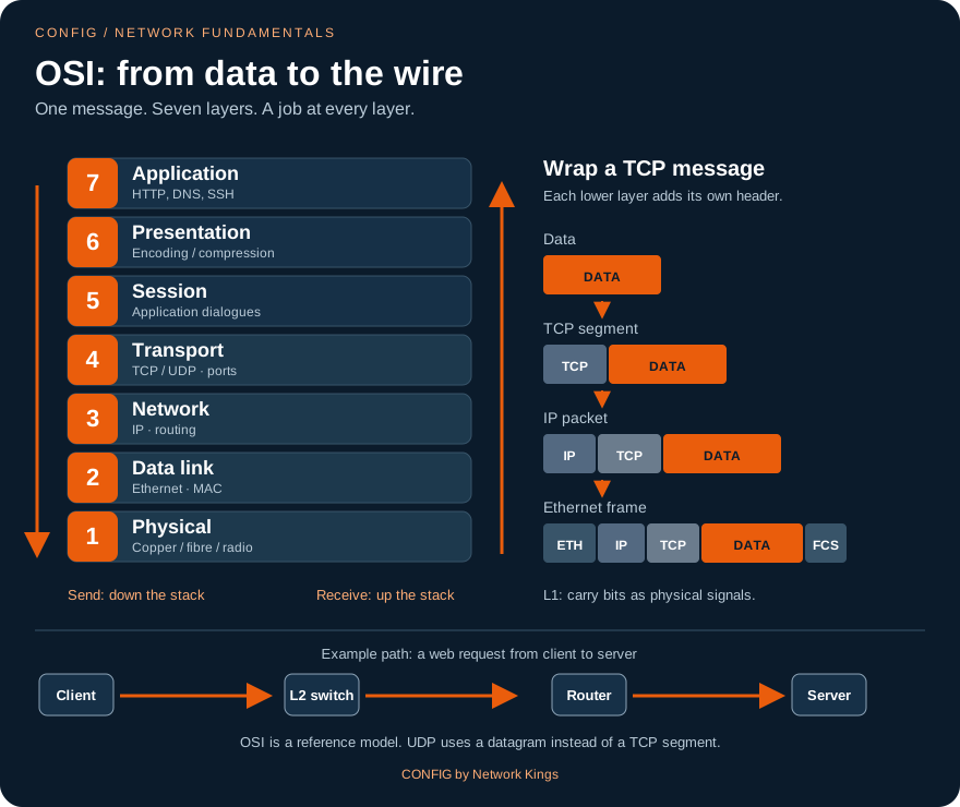
| OSI layer | Name | Job in one line | Unit of data (PDU) | Example |
|---|---|---|---|---|
| 7 | Application | Gives network services to applications | Data | Web, DNS, email |
| 6 | Presentation | Formats, encrypts, compresses | TLS encryption, JPEG | |
| 5 | Session | Opens and closes conversations | Session setup | |
| 4 | Transport | Delivery between applications, using ports | Segment (TCP) / datagram (UDP) | TCP, UDP |
| 3 | Network | End-to-end delivery across networks, using IP | Packet | IPv4, IPv6, routers |
| 2 | Data link | Delivery to the next device on the link, using MAC | Frame | Ethernet, Wi-Fi, switches |
| 1 | Physical | Bits as signals on the medium | Bits | Cables, fibre, radio, hubs |
The OSI model has 7 layers and is the teaching reference. The TCP/IP model, which the internet actually uses, merges layers 5, 6 and 7 into one Application layer, giving 4 layers (Application, Transport, Internet, Link) or 5 if you split Link into Data link and Physical. A popular way to remember OSI from layer 1 up: "Please Do Not Throw Sausage Pizza Away". The CCNA models module and the Network+ concepts module go through every layer in depth; here you only need the idea.
Encapsulation: envelopes inside envelopes
On the way down the layers at the sender, each layer adds its own header in front of what it received. This is encapsulation. On the way up at the receiver, each layer reads and removes its own header. This is de-encapsulation.
Each layer wraps the one above. The Ethernet frame also adds a trailer (FCS) used to detect damaged frames.
A web page load, step by step
Let us follow Asha's laptop (192.168.1.23/24, gateway 192.168.1.1, DNS 198.51.100.53) opening the secure web page www.nkshop.example.
- DNS lookup. The browser needs an IP address. The laptop sends a DNS query (UDP, port 53) to 198.51.100.53 and receives the answer 203.0.113.80.
- Local or remote? The laptop compares the destination with its own network using the mask. 203.0.113.80 is not in 192.168.1.0/24, so the packet must go to the default gateway.
- ARP. To build an Ethernet frame the laptop needs the gateway's MAC. It broadcasts an ARP (Address Resolution Protocol) request, "who has 192.168.1.1?", and the router replies with its MAC. The laptop stores it in its ARP cache. (Strictly, ARP also happened before the DNS query in step 1, because the DNS server is remote too; after the first time the answer is cached.)
- TCP three-way handshake. The laptop opens a reliable connection to 203.0.113.80 port 443: SYN, the server answers SYN-ACK, the laptop sends ACK.
- Secure session. The browser and server agree on encryption keys (TLS), so nobody on the path can read the page.
- The request and the page. The browser sends an HTTP request ("GET the home page"); the server returns the page, often followed by more requests for images and scripts.
- At every router on the way, the frame is removed, the router looks at the destination IP, lowers the TTL (time to live) by 1, and builds a new frame with new source and destination MACs for the next link. The IP addresses stay the same end to end (except where NAT changes them, as at Asha's home router).
You can see step 3 on your own PC with arp -a:
Interface: 192.168.1.23 --- 0xc
  Internet Address      Physical Address      Type
  192.168.1.1           a4-91-b1-3e-00-01     dynamic
  192.168.1.255         ff-ff-ff-ff-ff-ff     static
Worked example: what changes on each hop. Asha's frame to her router: source MAC 3c52.821a.2b3c, destination MAC a491.b13e.0001, source IP 192.168.1.23, destination IP 203.0.113.80. After NAT, on the ISP link: new source MAC (the router's outside port), new destination MAC (the ISP router), source IP 198.51.100.24, destination IP still 203.0.113.80. MACs change every hop; the destination IP never does.
Common beginner mistake. Thinking the PC ARPs for the remote server's MAC. It never does: a PC only ARPs for addresses on its own network. For anything remote, it ARPs for the default gateway.
Exam trap. Match PDUs to layers: segment = Layer 4, packet = Layer 3, frame = Layer 2, bits = Layer 1. Routers rewrite the Layer 2 header at every hop but keep the Layer 3 destination. TCP handshake order: SYN, SYN-ACK, ACK.
Local printer works, internet does not
A new PC could print to the printer 192.168.1.50 and reach the file server 192.168.1.10, but no website opened and ping 203.0.113.80 said "transmit failed". The engineer ran ipconfig: IP 192.168.1.40 and mask 255.255.255.0 were correct, but the Default Gateway line was empty. A technician had typed a static address and skipped the gateway field. The PC correctly decided in step 2 that the server was remote, but it had no router to hand the packet to. Adding gateway 192.168.1.1 fixed it instantly.
Lesson: local traffic needs only a correct IP and mask; anything remote also needs a correct default gateway.
"Explain encapsulation, and tell me what changes and what stays the same as a packet crosses routers."
Strong answer: each layer adds its own header as data goes down the stack: data, then a TCP or UDP segment with ports, then an IP packet with source and destination IP, then an Ethernet frame with MACs and an FCS trailer, then bits. At each router the frame is stripped, the router routes on the destination IP, decrements TTL and builds a new frame with new MACs for the next link. IP addresses stay the same end to end unless NAT changes them. Walk through a real example with ARP for the gateway.
Key takeaways
- OSI has 7 layers; TCP/IP has 4 (or 5). Remember "Please Do Not Throw Sausage Pizza Away".
- Encapsulation adds headers going down; de-encapsulation removes them going up.
- PDUs: data, segment (L4), packet (L3), frame (L2), bits (L1).
- Web page load: DNS, local-or-remote check, ARP for the gateway, TCP handshake, TLS, request and response.
- At each router hop the MACs change; the destination IP does not; TTL drops by 1.
Protocols and standards; TCP vs UDP
When you call someone, you both follow unwritten rules. The caller waits for "Hello?", then introduces themselves; if the line breaks, one of you says "Can you hear me?" and repeats the last sentence; at the end you both say goodbye before hanging up. Nobody taught you this in school, yet if one person ignored the rules the conversation would fail. Computers cannot guess, so their rules must be written down precisely. A written set of rules for communication is called a protocol.
What a protocol defines
A protocol specifies:
- Format: which fields a message has, in what order and how many bits each (for example the source and destination IP fields in an IP header).
- Sequence: who speaks first and what the reply must be (for example SYN, SYN-ACK, ACK).
- Timing: how long to wait for a reply before trying again.
- Error handling: what to do if a message is lost, damaged or unexpected.
Because a protocol is precise, a phone from one company, a router from another and a server from a third can all talk to each other.
Standards and who writes them
A standard is a protocol or specification that an official body has published so anyone can build to it. Open standards are the reason networks from different vendors interoperate.
| Body | What it standardises | Examples you will meet |
|---|---|---|
| IEEE | Layers 1 and 2: cables, Ethernet, Wi-Fi | 802.3 (Ethernet), 802.11 (Wi-Fi), 802.1Q (VLAN tags), 802.3af/at/bt (PoE) |
| IETF | Internet protocols, published as numbered RFCs (Requests for Comments) | IP, TCP, UDP, DNS, DHCP, OSPF, BGP; RFC 1918 private addresses |
| ISO | International standards in general | The OSI reference model |
| TIA/EIA | Building cabling | TIA-568 (T568A/T568B wiring, 100 m channel) |
| ITU-T | Telecommunications | Many WAN and optical transport standards |
| IANA and the RIRs | Numbers, not protocols | Port numbers, IP address blocks (APNIC serves the Asia-Pacific region, including India) |
A proprietary protocol belongs to one vendor. For example, Cisco's CDP discovers neighbouring Cisco devices, while the open-standard LLDP (IEEE 802.1AB) does the same across vendors. In mixed networks, engineers prefer open standards.
Common protocols and their jobs
| Protocol | Layer | Job |
|---|---|---|
| Ethernet / Wi-Fi | 1-2 | Move frames on a wired or wireless link |
| ARP | 2/3 | Find the MAC address for an IPv4 address on the LAN |
| IP (IPv4, IPv6) | 3 | Address and route packets end to end |
| ICMP | 3 | Error and test messages; ping and traceroute use it |
| TCP / UDP | 4 | Deliver data to the right application (ports), reliably or quickly |
| DNS | 7 | Names to IP addresses (port 53) |
| DHCP | 7 | Automatic addressing (UDP 67/68) |
| HTTP / HTTPS | 7 | Web pages and APIs (TCP 80 / 443) |
| SSH / Telnet | 7 | Remote command line; SSH is encrypted (22), Telnet is plain text (23) |
| FTP / SFTP / TFTP | 7 | File transfer (21, SFTP runs over SSH 22, TFTP UDP 69) |
| SMTP / IMAP / POP3 | 7 | Send email (25/587) and read it (143/993, 110/995) |
| NTP, SNMP, Syslog | 7 | Time sync (UDP 123), monitoring (UDP 161/162), logs (UDP 514) |
TCP vs UDP: registered post vs a loudspeaker announcement
Both TCP and UDP work at Layer 4 and both use port numbers. The difference is how much care they take.
TCP (Transmission Control Protocol) is like registered post with acknowledgement. It first opens a connection with the three-way handshake. It numbers every byte (sequence numbers), the receiver confirms what arrived (acknowledgements), anything missing is retransmitted, data is put back in order, and a window controls how fast the sender may go (flow control). The price is more overhead (a header of at least 20 bytes) and some delay.
UDP (User Datagram Protocol) is like a loudspeaker announcement: it just sends. No connection, no acknowledgement, no retransmission, no ordering, and a tiny 8-byte header. If something is lost, the application decides whether to care. That makes UDP ideal where speed matters more than perfection, or where the application handles reliability itself.
TCP spends a round trip setting up before any data moves; UDP sends immediately.
| TCP | UDP | |
|---|---|---|
| Connection | Yes (three-way handshake) | No |
| Reliability | ACKs, retransmission, ordering | None built in |
| Header size | 20 bytes or more | 8 bytes |
| Typical uses | Web, email, file transfer, SSH | DNS queries, DHCP, voice and video calls, live streaming, online games, TFTP, SNMP, syslog |
You can see live TCP connections on Windows with netstat -an:
  Proto  Local Address          Foreign Address        State
  TCP    192.168.1.23:51514     203.0.113.80:443       ESTABLISHED
  TCP    192.168.1.23:51520     203.0.113.80:443       TIME_WAIT
  UDP    0.0.0.0:5353           *:*
The first line is Asha's browser (ephemeral port 51514) connected to the web server on port 443. UDP lines have no state, because UDP has no connections.
Worked example. In a video call, one lost voice packet causes a tiny click. If the call used TCP, the lost packet would be retransmitted and everything behind it would wait, so the voice would freeze for a moment, which is much worse. That is why voice uses UDP. Downloading a 2 GB software file is the opposite: one missing byte ruins the file, so it uses TCP.
Common beginner mistake. Saying "UDP is unreliable, so it is bad". UDP is simply lightweight; the application chooses. DNS uses UDP for quick queries and falls back to TCP for large answers and zone transfers.
Exam trap. Know which protocols are TCP vs UDP and their ports: DNS 53 (UDP mainly, also TCP), DHCP 67/68 UDP, TFTP 69 UDP, SNMP 161/162 UDP, Syslog 514 UDP, NTP 123 UDP; SSH 22, Telnet 23, SMTP 25, HTTP 80, HTTPS 443 on TCP. IEEE = Layers 1-2 (802.x); IETF = RFCs.
Choppy calls after a "security hardening"
After a firewall change, staff complained that softphone calls connected but the audio was one-way or silent. The engineer compared the new rule set with the old one and found that the admin had allowed only TCP to the voice provider, believing "TCP is safer". Call signalling worked over TCP, but the voice itself (RTP) travels over UDP on a range of ports, and it was now blocked. Allowing the provider's documented UDP port range restored clear audio.
Lesson: know which transport each application needs. Blocking UDP breaks real-time voice and video, DNS and DHCP.
"What is the difference between TCP and UDP? Give examples of applications for each."
Strong answer: both are Layer 4 and use ports. TCP is connection-oriented: three-way handshake, sequence numbers, acknowledgements, retransmission, ordering and flow control, so it suits web, email, file transfer and SSH. UDP is connectionless with an 8-byte header and no delivery guarantees, so it suits latency-sensitive or simple request/response traffic: voice and video, live streaming, DNS queries, DHCP, SNMP, syslog, TFTP. Mention that applications on UDP can add their own reliability if needed.
Key takeaways
- A protocol defines format, sequence, timing and error handling; a standard is a published protocol anyone can build to.
- IEEE = Ethernet/Wi-Fi (802.x); IETF = internet protocols (RFCs); ISO = OSI model; TIA = cabling; IANA/RIRs = numbers.
- Know the common protocols with their layer, job and port.
- TCP: connection, ACKs, retransmission, ordering, flow control. UDP: fast, 8-byte header, no guarantees.
- Voice, video, DNS, DHCP rely on UDP; web, email, file transfer and SSH rely on TCP.
Topologies and network architectures
Look at a city map from above. Some neighbourhoods have all lanes leading to one central market (a star). Some old towns have one long main road with every shop along it (a bus). A ring road circles the city. And between big cities, highways link almost every city to every other (a mesh). A topology is exactly this: the shape of how devices are connected. Choosing the shape decides how much the network costs, how fast it is and what happens when one piece breaks.
Physical vs logical topology
The physical topology is how the cables actually run. The logical topology is how data flows. They can differ: an old hub looked like a star physically (every cable to one box) but behaved like a bus logically (every signal went to every device). Diagrams you draw at work usually show one or the other, so always ask which.
The four classic shapes. Modern LANs are stars; WAN cores are often partial meshes.
The classic topologies
- Bus (history)
- All devices tapped onto one shared coaxial cable with a terminator at each end. Only one device could talk at a time, collisions were common, and one break in the cable stopped everyone. Used by early Ethernet (10BASE5, 10BASE2). You will only meet it in exams and old buildings.
- Ring (history)
- Each device connects to two neighbours, forming a loop; data passes around the ring. Token Ring and FDDI used a token that gave permission to transmit. A single break could stop the ring, so FDDI used a dual ring. Ring ideas survive in some metro and ISP fibre rings.
- Star
- Every device has its own cable to a central switch. One broken cable affects only one device, and adding devices is easy. This is how almost every LAN is built today. The weak point is the central switch, so important sites use two.
- Extended star / hierarchical
- Stars connected to bigger stars: floor switches connect to building switches, which connect to a core. This is simply a star of stars.
- Mesh
- In a full mesh every node connects to every other node: maximum redundancy, maximum cost. The number of links is n(n-1)/2. A partial mesh connects only the important nodes to each other.
- Hub-and-spoke
- Branches (spokes) connect to a central site (hub), typical for company WANs. Cheap and simple, but branch-to-branch traffic goes through the hub.
- Point-to-point
- A single link between exactly two devices, such as two routers joined by a WAN circuit.
- Hybrid
- A mix of the above, which is what every real network is.
Worked example: the cost of a full mesh. A company has 5 offices. A full mesh needs 5 x 4 / 2 = 10 links. With 10 offices: 10 x 9 / 2 = 45 links. With 20 offices: 20 x 19 / 2 = 190 links. That is why large WANs use hub-and-spoke or partial mesh, and keep full mesh for a few core sites.
Architectures: small office, campus, data center
| Environment | Typical design | Key idea |
|---|---|---|
| SOHO (small office/home office) | One all-in-one router with Wi-Fi, maybe one small switch | Simple and cheap; one box is a single point of failure |
| Campus (large office, college) | Three-tier: access, distribution, core | Access switches connect users; distribution aggregates a building and applies policy; core is a fast backbone between buildings |
| Collapsed core (medium site) | Two tiers: access plus a combined distribution/core | Saves money where a separate core is not needed |
| Data center | Spine-leaf: every leaf switch connects to every spine switch | Any server reaches any other in the same number of hops; built for east-west traffic |
Two direction words appear everywhere: north-south traffic enters or leaves a site (users to the internet), while east-west traffic stays inside (server to server). Modern applications create far more east-west traffic, which is why data centers moved to spine-leaf.
Three-tier campus: users plug into access, distribution aggregates, core joins buildings. Real designs double every uplink.
Wired or wireless?
Wired links are faster, more stable, lower in latency and harder to eavesdrop on. Wireless gives mobility and saves cabling, but it is shared, affected by walls and interference, and needs strong security. Most sites use both: wired for desks, servers, printers and APs; wireless for laptops and phones. Wi-Fi normally runs in infrastructure mode (clients join an AP); ad hoc mode (devices talk directly) is rare in business.
Common beginner mistake. Believing a star is fully redundant. In a star, the central switch and the single uplink are single points of failure. Real designs add a second switch and a second uplink, which turns part of the network into a mesh.
Exam trap. Full mesh links = n(n-1)/2. A bus needs terminators and one break stops everything. Three-tier = access, distribution, core; collapsed core merges distribution and core; spine-leaf = every leaf to every spine, never leaf to leaf.
Every branch went down when head office did
A retail chain connected 40 stores to head office in a hub-and-spoke WAN, and store-to-store video calls also passed through head office. When head office lost power for two hours, every store lost billing, stock checks and calls, even though the stores' own internet links were fine. The redesign gave each store direct internet access for cloud apps, added a second data center as a backup hub, and kept a small partial mesh between regional stores.
Lesson: topology decides what fails together. Know your single points of failure before they find you.
"Which topology do modern LANs use, and what are the trade-offs of a full mesh?"
Strong answer: modern LANs are physically a star (or extended star): each device has its own cable to an access switch, so one cable fault affects one device and growth is easy. A full mesh gives the most redundancy and shortest paths, but the number of links grows as n(n-1)/2, so cost and complexity explode; it is used between a few critical core nodes, while larger WANs use partial mesh or hub-and-spoke. Mention three-tier and spine-leaf as the campus and data center designs.
Key takeaways
- Topology = the shape of connections; physical (cables) and logical (data flow) may differ.
- Bus and ring are history; star is today's LAN; mesh gives redundancy at n(n-1)/2 links.
- WANs often use hub-and-spoke, point-to-point or partial mesh.
- Campus: three-tier (access, distribution, core) or collapsed core. Data center: spine-leaf for east-west traffic.
- Wired = speed and stability; wireless = mobility; real sites use both.
Your PC toolkit and a first troubleshooting workflow
A doctor does not guess. She checks your pulse, temperature and blood pressure first, in the same order every time, and only then decides. Network engineers work the same way, and their stethoscope is the command line: a text window where you type commands and read the answers. In this chapter you will open it on your own computer, learn five commands that every engineer uses daily, and follow a simple step-by-step method to find almost any "my internet does not work" problem.
Opening the command line
- Windows: press the Windows key, type
cmdand press Enter. A black window called Command Prompt opens (PowerShell or Windows Terminal work too). - macOS: open Spotlight (Cmd + Space), type
Terminal, press Enter. - Linux: press Ctrl + Alt + T on most desktops.
Type a command, press Enter, read the output. Nothing you do in this chapter changes your PC except ipconfig /release, which briefly disconnects you.
1. See your addresses: ipconfig, ip, ifconfig
| Command | System | What it shows or does |
|---|---|---|
ipconfig | Windows | IP address, mask and default gateway of each adapter |
ipconfig /all | Windows | Adds MAC, DHCP server, DNS servers and lease times |
ipconfig /release then ipconfig /renew | Windows | Give the DHCP address back, then ask for one again |
ipconfig /flushdns | Windows | Forget cached DNS answers |
ip addr (or ip a) and ip route | Linux | Addresses, and the routing table with the default gateway |
ifconfig | macOS, older Linux | Addresses and MAC of each interface |
C:\Users\asha> ipconfig

Wireless LAN adapter Wi-Fi:

   Connection-specific DNS Suffix  . : home.example
   IPv4 Address. . . . . . . . . . . : 192.168.1.23
   Subnet Mask . . . . . . . . . . . : 255.255.255.0
   Default Gateway . . . . . . . . . : 192.168.1.1
asha@laptop:~$ ip addr show wlan0
3: wlan0: <BROADCAST,MULTICAST,UP,LOWER_UP> mtu 1500 qdisc noqueue state UP group default qlen 1000
    link/ether 3c:52:82:1a:2b:3c brd ff:ff:ff:ff:ff:ff
    inet 192.168.1.23/24 brd 192.168.1.255 scope global dynamic wlan0
asha@laptop:~$ ip route
default via 192.168.1.1 dev wlan0 proto dhcp metric 600
192.168.1.0/24 dev wlan0 proto kernel scope link src 192.168.1.23 metric 600
2. Test reachability: ping
ping sends ICMP echo requests and waits for echo replies. Windows sends 4 and stops; Linux and macOS keep going until you press Ctrl + C (use -c 4 to send 4).
C:\Users\asha> ping 192.168.1.1

Pinging 192.168.1.1 with 32 bytes of data:
Reply from 192.168.1.1: bytes=32 time=2ms TTL=64
Reply from 192.168.1.1: bytes=32 time=1ms TTL=64
Reply from 192.168.1.1: bytes=32 time=3ms TTL=64
Reply from 192.168.1.1: bytes=32 time=1ms TTL=64

Ping statistics for 192.168.1.1:
    Packets: Sent = 4, Received = 4, Lost = 0 (0% loss),
Approximate round trip times in milli-seconds:
    Minimum = 1ms, Maximum = 3ms, Average = 1ms
Learn to read the three classic failures: Request timed out (no reply came back; the target is down, blocked by a firewall, or the reply has no route home), Destination host unreachable (a device, often your own PC or a router, knows it cannot deliver), and Ping request could not find host (the name could not be resolved: DNS).
3. See the path: tracert / traceroute
C:\Users\asha> tracert www.nkshop.example

Tracing route to www.nkshop.example [203.0.113.80]
over a maximum of 30 hops:

  1     1 ms     1 ms     1 ms  192.168.1.1
  2     8 ms     7 ms     9 ms  198.51.100.1
  3    12 ms    11 ms    12 ms  198.51.100.66
  4     *        *        *     Request timed out.
  5    24 ms    23 ms    25 ms  203.0.113.80

Trace complete.
Each line is one router (hop). It works by sending packets with TTL 1, 2, 3 and so on; each router that drops a packet because its TTL reached zero sends back an ICMP "time exceeded" message and so reveals itself. A single line of stars in the middle, followed by answers, is normal: that router simply does not reply to traceroute. Stars from some hop to the end mean the path breaks there. Windows tracert uses ICMP; Linux and macOS traceroute use UDP by default.
4. Test DNS: nslookup
C:\Users\asha> nslookup www.nkshop.example
Server:  resolver.isp.example
Address:  198.51.100.53

Non-authoritative answer:
Name:    www.nkshop.example
Address:  203.0.113.80
"Non-authoritative" just means the answer came from the resolver's cache, not from the domain's own server. Two more handy commands: arp -a (the ARP cache, chapter 7) and netstat -an (open connections, chapter 8).
The troubleshooting workflow: bottom-up, one step at a time
Climb from the bottom. The first step that fails is where you dig.
- Physical. Is the cable plugged in with a link light on the port? Is Wi-Fi connected to the right network? Is airplane mode off?
- Addressing. Run
ipconfig. A 169.254.x.x address means the PC could not reach a DHCP server. A missing gateway, or a gateway in a different network, breaks everything remote. - Gateway.
ping 192.168.1.1. If this fails, the problem is on your local LAN or the link to it. - Beyond the gateway. Ping a remote IP address, such as your DNS server. If the gateway answers but this fails, suspect the router, the ISP link or routing. Use
tracertto see where it stops. - Names.
nslookupa name. If IPs work but names fail, it is DNS. - Application. If all of the above work, the network is fine for this PC; look at the application, its server, or a firewall rule for that port.
This is the bottom-up approach, following the layers from chapter 7. Formal methods add structure around it; the CompTIA method is: identify the problem, establish a theory of probable cause, test the theory, establish a plan of action, implement the solution or escalate, verify full system functionality and add preventive measures, and document findings. Always ask "what changed recently?" and always write down what you did.
Worked example. Ravi says "no internet". Step 1: Wi-Fi shows connected. Step 2: ipconfig shows 192.168.1.40/24, gateway 192.168.1.1. Step 3: ping 192.168.1.1 gets 4 replies. Step 4: ping 198.51.100.53 gets 4 replies. Step 5: nslookup www.nkshop.example times out with "DNS request timed out". Diagnosis in two minutes: DNS. He had a manual DNS server that no longer exists; setting DNS back to automatic fixed it.
Common beginner mistake. Jumping to the top ("reinstall the browser", "restart the router") before checking the bottom. Another: concluding a server is down because ping times out. Many servers and firewalls block ICMP on purpose; test the actual service too.
Exam trap. 169.254.x.x = APIPA, DHCP unreachable. Works by IP but not by name = DNS. Windows: tracert, ipconfig; Linux: traceroute, ip addr/ifconfig. Know the CompTIA troubleshooting steps in order; "verify full system functionality" comes after implementing the fix, and "document" is last.
The whole floor got 169.254 addresses
On Monday morning every PC on the third floor showed "No internet". The engineer asked one user to run ipconfig: IPv4 address 169.254.37.112, mask 255.255.0.0, no gateway. Other floors were fine. Since the whole floor failed DHCP at once, the problem was shared, not on each PC. In the rack, the floor switch's uplink cable had been knocked out during weekend cleaning. Plugging it back in and running ipconfig /renew gave everyone valid addresses.
Lesson: one user failing points at that user; many users failing together points at what they share. APIPA tells you DHCP never answered.
"A user says the internet is not working. Walk me through how you would troubleshoot."
Strong answer: start by asking what exactly fails and what changed. Then go bottom-up: check the link or Wi-Fi, run ipconfig for a valid IP, mask, gateway and DNS (169.254 means DHCP failed), ping the gateway, ping a remote IP, run tracert to see where the path stops, then nslookup to test DNS, and finally the application or firewall. Check whether other users are affected to decide between a local and a shared problem. Fix, verify, and document.
Key takeaways
- ipconfig (/all, /release, /renew, /flushdns), ip addr/ip route or ifconfig show your addressing.
- ping tests reachability; read "timed out", "unreachable" and "could not find host" differently.
- tracert/traceroute shows each hop using TTL; nslookup tests DNS.
- Troubleshoot bottom-up: physical, IP config, gateway, remote IP, DNS, application.
- Many users failing together means a shared cause; always verify and document.
Using the lab simulator, and a first look at the Cisco CLI
Pilots do not learn to fly on a real plane full of passengers. They spend hours in a flight simulator, where they can make mistakes, crash, press reset and try again. This academy's lab simulator is your flight simulator for networks. Real routers and switches cost lakhs of rupees and a mistake on a live network can stop a business; in the simulator you can configure, break and fix as often as you like, straight from your browser, with nothing to install.
Where things are: the module page
Every module page has the same tabs you met in chapter 1: Lesson (these chapters), Labs, Quiz, Scenarios and Interview. Open a lab from the Labs tab. The next module on your track (Cisco IOS from zero for CCNA, or the OSI and protocols module for Network+) is where you start using labs for real, so this chapter prepares you for that first session.
The lab screen
A simplified view. Tasks on one side, the topology and a console for the selected device on the other.
- Topology map
- The drawing of the lab: PCs, switches, routers and the cables between them. Links show their state (up, down, or blocked). Click a device to switch the console to it.
- Console
- The terminal of the selected device. You type exactly the commands you would type on real equipment, and the simulator answers with realistic output.
- Tasks
- What the lab asks you to achieve. Each task is checked live against the running devices, so it passes only when the network really works, not when you type a particular word. When all tasks pass, the lab is complete.
- Hint and Solution
- Stuck? Open a hint first; it points you in the right direction. Open the solution only after a genuine attempt, then close it and redo the task from memory.
- Reset
- Puts every device back to the starting state (click twice to confirm). Break things freely; you can always reset.
- Capture packets
- Shows the packets on the links (ARP, ICMP, routing hellos) while you work, like a built-in packet analyser. It turns chapter 7 into something you can watch.
After many labs you will also see a short set of exam-style questions to test yourself. There is also a Build your own lab sandbox where you add devices, cable them (click the first device, then the second) and double-click a device to open its console.
The simulated PC
PCs in the simulator use a small, fast command shell modelled on the virtual PCs found in popular network emulators, rather than full Windows. Type ? to list its commands.
! give PC1 a static address, mask (/24) and gateway
ip 192.168.10.10/24 192.168.10.1
! or ask a DHCP server instead
ip dhcp
! check the settings, then test
show ip
ping 192.168.10.1
trace 203.0.113.80
arp
PC1> ip 192.168.10.10/24 192.168.10.1
Checking for duplicate address...
PC1 : 192.168.10.10 255.255.255.0 gateway 192.168.10.1

PC1> show ip
NAME        : PC1[1]
IP/MASK     : 192.168.10.10/24
GATEWAY     : 192.168.10.1
DNS         :
MAC         : 00:50:79:66:68:00
MTU         : 1500

PC1> ping 192.168.10.1
84 bytes from 192.168.10.1 icmp_seq=1 ttl=255 time=0.500 ms
84 bytes from 192.168.10.1 icmp_seq=2 ttl=255 time=0.600 ms
84 bytes from 192.168.10.1 icmp_seq=3 ttl=255 time=0.700 ms
84 bytes from 192.168.10.1 icmp_seq=4 ttl=255 time=0.800 ms
84 bytes from 192.168.10.1 icmp_seq=5 ttl=255 time=0.900 ms
A failed ping shows lines such as 192.168.10.1 icmp_seq=1 timeout. With DHCP, success looks like DDORA IP 192.168.10.11/24 GW 192.168.10.1: the letters are the Discover, Offer, Request and Acknowledge steps from chapter 6. In labs that include a DNS server, nslookup and pinging by name also work.
A first look at the Cisco CLI
Switches and routers in the CCNA labs use the Cisco IOS command line. It has modes, like rooms in a building, and the prompt tells you which room you are in:
| Mode | Prompt | How to enter | What you can do |
|---|---|---|---|
| User EXEC | R1> | You start here | A few basic show commands |
| Privileged EXEC | R1# | enable | All show commands, save, reload |
| Global configuration | R1(config)# | configure terminal | Change settings for the whole device |
| Interface configuration | R1(config-if)# | interface gigabitethernet0/0 | Change one port |
exit goes back one level; end jumps straight to privileged EXEC. Type ? anywhere for help, and press Tab to complete a command. Here is a taste of what you will do in the next CCNA module:
Router> enable
Router# configure terminal
Enter configuration commands, one per line.  End with CNTL/Z.
Router(config)# hostname R1
R1(config)# interface gigabitethernet0/0
R1(config-if)# ip address 192.168.10.1 255.255.255.0
R1(config-if)# no shutdown
R1(config-if)# end
R1# show ip interface brief
Interface              IP-Address      OK? Method Status                Protocol
GigabitEthernet0/0     192.168.10.1    YES manual up                    up
GigabitEthernet0/1     unassigned      YES unset  administratively down down
R1# copy running-config startup-config
Destination filename [startup-config]?
Building configuration...
[OK]
Do not worry about memorising this yet. Notice only the pattern: move into the right mode, change something, verify with a show command, and save.
Worked example: your first lab routine. 1) Read all the tasks before typing. 2) Click each device on the map and look around with show commands (or show ip on PCs). 3) Do one task at a time and verify it immediately with ping or a show command. 4) If a task does not pass, re-read it and use a hint. 5) When the lab is complete, break something on purpose (shut an interface, change a gateway) and watch what fails. That last step teaches troubleshooting better than anything else.
Common beginner mistake. Typing configuration commands in the wrong mode. ip address fails at R1# with "Invalid input detected" because it belongs in interface configuration mode. Always read the prompt before you type.
Exam trap. Know the mode order and prompts: > user EXEC, # privileged EXEC, (config)# global, (config-if)# interface. enable moves from user to privileged; configure terminal from privileged to global. Changes live in the running-config until you copy them to the startup-config.
"The lab is broken, my task will not pass"
A learner wrote to support: every command was accepted, but task 2 ("PC1 can ping R1") would not pass. The support engineer looked at the attempt: PC1 had ip 192.168.10.10/24 192.168.1.1, a gateway from a different network, which the PC rejected, so the learner re-entered it without a gateway. The router's interface was also still administratively down because no shutdown had been skipped. The live check was right: the ping really failed. Fixing both made the task pass instantly.
Lesson: live checks test the network, not your typing. When a task does not pass, verify with ping and show commands, exactly as on the job.
"How do you practise networking without real equipment?"
Strong answer: use a simulator or emulator to build topologies, configure devices from the CLI and, most importantly, break and fix them. Explain your routine: read the requirement, configure step by step, verify each step with ping and show commands, capture packets to see what really happens, then introduce faults and troubleshoot. Mention that you document what you learn. Interviewers look for hands-on habits, not just certificates.
Key takeaways
- A lab screen has a topology map, a console per device, and tasks checked live; plus hint, solution, reset and packet capture.
- Simulated PCs:
ip A.B.C.D/M GW,ip dhcp,show ip,ping,trace,arp,?. - Cisco IOS modes:
>user,#privileged,(config)#global,(config-if)#interface. - Pattern for every change: right mode, configure, verify with show/ping, save.
- Use hints before solutions, and break the lab on purpose once it works.
Careers, the road ahead, summary and checklist
You have just finished the foundation of a building. Nobody admires foundations, but every floor above depends on them: subnetting depends on binary, routing depends on addressing, troubleshooting depends on the layers, and every lab depends on the command line. This last chapter shows you the floors you can build next, the jobs they lead to, and a checklist to confirm your foundation is solid.
Jobs in networking
| Role | What you do day to day | Typical entry path |
|---|---|---|
| Help desk / desktop support | Fix user connectivity, Wi-Fi, IP settings, printers | This module, Network+ |
| NOC engineer (L1/L2) | Watch monitoring dashboards 24x7, handle alarms and tickets, escalate outages | Network+ or CCNA |
| Network engineer | Configure and troubleshoot switches, routers, VLANs, routing, VPNs | CCNA, then CCNP |
| Network security engineer | Firewalls, VPNs, access control, security monitoring | CCNA plus security certifications |
| Cloud network engineer | Virtual networks, hybrid links and security in public cloud | CCNA plus a cloud associate certification |
| Wireless / data center / automation | Specialist designs, fabrics, scripts and APIs | CCNP-level specialisation |
The certification road
Network+ and CCNA both start from this module; many engineers take one, some take both.
CompTIA Network+ is vendor-neutral and covers concepts, implementation, operations, security and troubleshooting. Cisco CCNA covers similar ground with far more hands-on configuration on Cisco devices. After either, the professional level (such as CCNP Enterprise or CCNP Security) and cloud or security certifications open specialist roles. Certifications open interview doors; lab skill and clear explanations get you the job.
How to study
- Little and daily beats long and rare: one chapter plus one lab a day moves faster than a weekend marathon.
- Follow the rhythm: lesson, labs, quiz, scenarios, interview. The quiz tells you what to re-read.
- Draw from memory the diagrams of each chapter; explain them out loud as if to a friend.
- Revisit binary and ports every few days until conversion is automatic.
- Break labs on purpose after completing them, and troubleshoot bottom-up.
Can-do checklist
Tick each one honestly. If you cannot do one, go back to the chapter in brackets.
- Explain what a network is and classify LAN, WAN, WLAN and the internet (1).
- Describe the path of a request from home to a data center, including DNS (2).
- Name switch, router, AP, firewall, modem and what each decides (3).
- Pick the right cable: Cat5e/6/6a, straight-through vs crossover, single-mode vs multimode (4).
- Convert any octet between binary, decimal and hex without a calculator (5).
- Explain MAC vs IP vs port, private ranges, APIPA and DHCP DORA (6).
- List the OSI layers with their PDUs and trace a web page load (7).
- Compare TCP and UDP and give the ports of common services (8).
- Draw star, mesh, three-tier and spine-leaf and name their trade-offs (9).
- Use ipconfig, ping, tracert and nslookup and troubleshoot bottom-up (10).
- Move around the simulator and the Cisco IOS modes (11).
Mini glossary
- APIPA
- Self-assigned 169.254.x.x address used when DHCP does not answer.
- ARP
- Finds the MAC address for an IPv4 address on the local network.
- Default gateway
- The router a host sends all non-local traffic to.
- DHCP
- Hands out IP, mask, gateway and DNS automatically (DORA).
- DNS
- Translates names into IP addresses.
- Encapsulation
- Each layer adding its header around the data from the layer above.
- Latency / bandwidth
- Delay of a trip / capacity of the link.
- NAT
- Replaces private addresses with a public one at the network edge.
- PDU
- The unit at each layer: data, segment, packet, frame, bits.
- TTL
- Hop counter in the IP header, reduced by 1 at each router.
Most tested facts
| Topic | Remember |
|---|---|
| Address sizes | MAC 48 bits, IPv4 32 bits, IPv6 128 bits, port 16 bits |
| Private IPv4 | 10.0.0.0/8, 172.16.0.0/12, 192.168.0.0/16; APIPA 169.254.0.0/16; loopback 127.0.0.1 |
| Copper | 100 m max; Cat6a = 10 Gbps at 100 m; straight = unlike devices, crossover = like devices |
| Fibre | SMF: laser, km, yellow; MMF: LED/VCSEL, hundreds of metres, aqua/orange |
| Devices | Hub L1, switch L2 (MAC table), router L3 (routing table) |
| Ports | SSH 22, Telnet 23, SMTP 25, DNS 53, DHCP 67/68, HTTP 80, HTTPS 443, RDP 3389 |
| TCP vs UDP | TCP handshake SYN, SYN-ACK, ACK; UDP 8-byte header, no ACKs |
| Mesh | n(n-1)/2 links |
Command cheat-sheet
! Your own PC
ipconfig /all
ping 192.168.1.1
tracert www.nkshop.example
nslookup www.nkshop.example
arp -a
! Simulator PC
ip 192.168.10.10/24 192.168.10.1
ip dhcp
show ip
! Cisco IOS (preview)
enable
configure terminal
show ip interface brief
copy running-config startup-config
Common beginner mistake. Rushing to "advanced" topics because the basics feel easy. Most failed interviews and most real outages trace back to basics: a wrong mask, a missing gateway, DNS, a bad cable.
Exam trap. Many exam questions hide a basic fact inside a long story. Strip the story, find the layer, then answer. "Works by IP not by name" is DNS; "169.254" is DHCP; "only one PC" is local; "everyone on the floor" is shared.
The fresher who got the NOC job
Two candidates interviewed for a NOC L1 role. The first listed many advanced acronyms but could not explain what happens when a PC gets 169.254.x.x. The second had only this foundation and one certification in progress, but calmly walked through ipconfig, ping to the gateway, tracert and nslookup, drew a home-to-data-center diagram, and converted an address to binary on the whiteboard. The second candidate got the offer.
Lesson: clear fundamentals and a method beat a list of buzzwords.
"Why did you choose networking, and how are you preparing?"
Strong answer: connect a genuine reason (every business runs on networks; you enjoy solving problems methodically) to concrete preparation: the fundamentals you can explain, the certification you are working on (Network+ or CCNA), the number of labs you have completed in a simulator, and a troubleshooting example you practised. Close with the role you want in two to three years. Specific beats enthusiastic.
Key takeaways
- Entry roles: help desk and NOC; then network, security, cloud and specialist engineering.
- Network+ (vendor-neutral) and CCNA (Cisco, hands-on) both build on this module; CCNP and beyond follow.
- Study little and daily, follow lesson, labs, quiz, scenarios, interview, and break labs on purpose.
- Use the checklist: every "no" points to a chapter to revisit.
- Next: Cisco IOS from zero (CCNA) or OSI, encapsulation, ports and protocols (Network+).