Jump to chapter (13)
The big picture: Networking Concepts for Network+
What you will learn in this module. This module covers the first and most heavily memorised domain of CompTIA Network+ N10-009: 1.0 Networking Concepts. By the end you will be able to explain every OSI layer with its PDU, headers, devices and failure symptoms; follow one packet through encapsulation and prove it with ARP caches, TTL values and routing tables; choose the right appliance or function (firewall, IDS/IPS, load balancer, proxy, NAS/SAN, CDN, VPN, QoS) for a business problem; recite the full N10-009 port table with transport protocols; recognise IP protocol types such as ICMP, GRE, ESP and AH; pick the right cable, fibre, transceiver and connector for a link; and describe mesh, star, spine-leaf, three-tier and collapsed-core designs and the traffic flows they are built for.
Prerequisites
You have finished the beginner module net-start. That means you already know what a network is, the difference between a switch and a router, what MAC, IP and port addresses are, the idea of layers and encapsulation, TCP versus UDP at a high level, the basic cable types and the classic topologies, and how to use ping, tracert and nslookup. We will not repeat those basics. Here we go one level deeper: header fields, exact numbers, standards, distances and the exam traps built around them.
An analogy: an international courier company
Imagine a courier company that ships a parcel from Delhi to a customer in Chennai. The sales desk takes the order and does not care about trucks (application). The packing team decides the box format and seals it (presentation). A booking clerk opens a shipment record and closes it when delivery is confirmed (session). The dispatch team splits a large order into numbered boxes and asks for a signed receipt for each one (transport). The routing office writes the final city address and picks the next hub (network). Each truck driver only knows how to get from this hub to the next one (data link). And the road itself carries the truck (physical).
No department does another department's job, and each one adds its own label to the box. That is exactly how the OSI model divides networking work, and it is why an engineer can say "the problem is at Layer 2" and every other engineer instantly knows where to look.
This module covers objectives 1.1, 1.2, 1.4, 1.5 and 1.6. Cloud (1.3), addressing (1.7) and IPv6 (1.8) have their own modules next.
Why this domain matters so much
Domain 1.0 is roughly a quarter of the exam, but its real weight is higher. The troubleshooting domain (5.0, the largest at about 24%) constantly asks "which layer is failing?", "which port is blocked?" or "which cable or transceiver is wrong for this distance?". If the facts in this module are automatic for you, those troubleshooting questions become easy. The exam has up to 90 questions in 90 minutes, including performance-based questions (PBQs) where you drag ports onto protocols or cables onto distances. There is no time to work these out from scratch.
In real jobs the same knowledge is how you write firewall rules (you must know that DNS uses UDP 53 and that IPsec needs UDP 500 plus ESP), how you order optics (a 10GBASE-LR module will not work on multimode fibre), and how you read a packet capture.
How this module is organised
- Chapters 2-4: the OSI layers in depth, bottom-up and top-down, then encapsulation hop by hop.
- Chapters 5-6: appliances (what each box decides and at which layer) and functions such as CDN, VPN, QoS and TTL.
- Chapters 7-9: ports and protocols with memory aids, then IP protocol types and traffic types.
- Chapters 10-11: transmission media, transceivers, connectors, then topologies and architectures.
- Chapter 12: a layer-by-layer troubleshooting workflow using the two labs.
- Chapter 13: summary, can-do checklist, glossary and the most tested facts.
The two labs
Both labs use the same small network: PC1 (10.0.10.10/24, gateway 10.0.10.1) connects through switch SW1 to router R1, which routes to the server SRV (10.0.20.10/24) on 10.0.20.0/24. In Follow a ping through the layers you will read PC1's ARP cache, watch the TTL drop from 64 to 63, and read R1's routing table. In Ports and protocols in action you will point PC1 at R1 as a DNS server, resolve web.nwk.lab and open it over HTTP and HTTPS while a capture shows the real transport and port numbers.
Worked example. A user says "the intranet is down". Using layers, you turn that into five quick questions: Is the link light on (L1)? Does the PC have the gateway MAC in its ARP cache (L2)? Does ping to 10.0.20.10 get a reply (L3)? Does a TCP connection to port 443 open (L4)? Does the name resolve and does the page load (L7)? If ping works but nslookup web.nwk.lab fails, you have narrowed a vague complaint to one service in under a minute.
Common mistake. Treating Network+ as a pure memorisation exam and learning port numbers as a list of digits. Questions are scenario-based: "users can browse by IP but not by name" or "the VPN tunnel will not form through the firewall". Learn each fact together with the symptom it causes when it is wrong.
Exam trap. CompTIA uses the OSI model, not the TCP/IP model, when it asks "at which layer". A question about a router is Layer 3, not "Internet layer". A question about TLS encryption is usually answered with Layer 6 (presentation) in CompTIA's view, even though TLS runs as part of the application in practice.
"The network is slow" at a branch office
A new NOC engineer received a ticket saying a branch "network is slow". He rebooted the branch router, which did nothing except drop every call for five minutes. A senior engineer took over and worked by layers: interface counters showed no CRC errors (L1 fine), the switch had no MAC flapping (L2 fine), pings to head office were 18 ms with no loss (L3 fine). A capture showed the file-share traffic on TCP 445 was retransmitting heavily only to one server, whose NIC was set to 100 Mb/s half duplex. Fixing the duplex setting on that server solved it.
Lesson: layered thinking turns a vague complaint into a short list of checks, and stops you from "fixing" things that are not broken.
"Why do we still learn the OSI model when real networks run TCP/IP?"
Strong answer: the OSI model is a shared vocabulary for design and troubleshooting. Vendors, documentation and colleagues say "Layer 2 issue", "Layer 4 load balancer" or "Layer 7 firewall", and those phrases come from OSI. TCP/IP is the protocol suite that actually runs; OSI is the reference map we use to describe where each function sits. Mention that you troubleshoot bottom-up or top-down by layer.
Key takeaways
- This module covers N10-009 objectives 1.1, 1.2, 1.4, 1.5 and 1.6; addressing, IPv6 and cloud come in the next modules.
- Each OSI layer is a department with one job and its own header, like a courier company.
- Domain 1.0 facts feed the troubleshooting domain; learn each fact with its failure symptom.
- CompTIA asks "which layer" in OSI terms.
- The two labs use PC1, SW1, R1 and SRV to make layers, TTL, ARP and ports visible.
OSI in depth, part 1: Physical, Data link and Network
In net-start you met the seven layers as names in a table. Now we open each of the lower three and look inside: what is actually on the wire, which header fields exist, which devices work there, and what a failure at that layer looks like. Think of the courier company again: this chapter is about the road, the truck driver and the routing office.
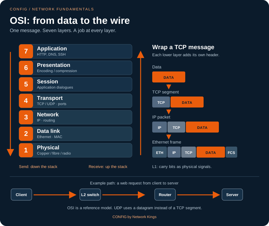
Layer 1, Physical: turning bits into signals
Layer 1 moves raw bits. It has no idea what a frame or an address is. Its job is to define how a 1 and a 0 look on the medium: voltage changes on copper, pulses of light on fibre, or changes in a radio wave for wireless. Layer 1 standards set the connector and pinout, the cable type and maximum length, the signalling and encoding (how bits are represented), the bit rate (1 Gb/s, 10 Gb/s) and the duplex (half duplex takes turns; full duplex sends and receives at the same time).
Devices and parts at Layer 1: cables, connectors, patch panels, hubs, repeaters, media converters (copper to fibre) and the transceiver side of an SFP module. A hub is simply a multiport repeater: it copies bits out of every port and understands nothing.
Layer 1 symptoms: no link light, interface down/down, CRC and input errors climbing, late collisions (a sign of a duplex mismatch), a link that negotiates at 100 Mb/s instead of 1 Gb/s because one pair of the cable is broken.
Layer 2, Data link: frames on one link
Layer 2 delivers a frame from one device to the next device on the same link or LAN. It adds physical addressing (48-bit MAC addresses) and error detection. IEEE splits it into two sublayers: LLC (Logical Link Control, 802.2) identifies what is carried inside, and MAC (Media Access Control) handles addressing and access to the medium. The first 24 bits of a MAC address are the OUI (Organisationally Unique Identifier) of the vendor; the last 24 bits are assigned by that vendor.
The fields you will be asked about: destination MAC first, EtherType, FCS at the end; TTL, Protocol and the two IP addresses in the IP header.
Walk through the frame from left to right. The preamble and SFD (8 bytes) let the receiver synchronise its clock. The destination MAC comes first so a switch can start its forwarding decision early. The 802.1Q tag (4 bytes, only on trunk links) carries the VLAN ID and a 3-bit priority value called CoS. The EtherType says what is inside: 0x0800 for IPv4, 0x0806 for ARP, 0x86DD for IPv6. The payload is 46 to 1500 bytes; 1500 is the standard MTU. The FCS (Frame Check Sequence) is a CRC value; a receiver that calculates a different value discards the frame and counts a CRC error. Ethernet detects errors but does not correct or resend them; that job belongs to TCP at Layer 4.
Devices at Layer 2: switches, bridges, wireless access points and NICs. A switch learns source MACs into its MAC address table and forwards by destination MAC. Broadcasts (FF:FF:FF:FF:FF:FF) and unknown destinations are flooded within the VLAN.
Layer 2 symptoms: a host is in the wrong VLAN, a trunk does not allow a VLAN, MAC flapping from a loop, ARP not resolving, a port in err-disabled state from port security.
Layer 3, Network: packets across networks
Layer 3 moves a packet from the original source to the final destination, across many links. It adds logical addressing (IPv4 or IPv6) and handles path selection (routing). Key IPv4 header fields: TTL (decremented by every router; at 0 the packet is dropped and an ICMP Time Exceeded is sent back), Protocol (which Layer 4 or other protocol is inside: 1 ICMP, 6 TCP, 17 UDP), DSCP (6 bits used by QoS), the identification, flags and fragment offset fields used for fragmentation (including the Don't Fragment bit), and the source and destination IP addresses.
Devices at Layer 3: routers, Layer 3 (multilayer) switches, and firewalls when they route. ICMP is a Layer 3 helper protocol used by ping and traceroute. ARP sits on the border: it serves Layer 3 (it is asked "what MAC belongs to this IP?") but works entirely inside one Layer 2 broadcast domain, and most exam material groups it with Layer 2.
Layer 3 symptoms: wrong mask or gateway on a host, a missing route, a routing loop (TTL expiring in transit), an ACL dropping packets, MTU problems when DF is set.
Worked example. PC1 (10.0.10.10) sends 1000 bytes of data to SRV (10.0.20.10) with TCP. TCP adds 20 bytes (segment = 1020), IP adds 20 bytes (packet = 1040), Ethernet adds 14 bytes of header and 4 bytes of FCS (frame = 1058 bytes, plus 8 bytes of preamble on the wire). The IP packet's Protocol field is 6 (TCP) and the frame's EtherType is 0x0800 (IPv4).
Seeing Layers 1 and 2 on a router interface
! on R1: one command shows Layer 1 and Layer 2 health
R1# show interfaces GigabitEthernet0/0
GigabitEthernet0/0 is up, line protocol is up
  Hardware is iGbE, address is 5254.0012.3456 (bia 5254.0012.3456)
  Internet address is 10.0.10.1/24
  MTU 1500 bytes, BW 1000000 Kbit/sec, DLY 10 usec,
  Full-duplex, 1000Mb/s, media type is RJ45
     0 input errors, 0 CRC, 0 frame, 0 overrun, 0 ignored
     0 output errors, 0 collisions, 1 interface resets
The first word pair is the Layer 1 status ("is up"), the second is Layer 2 ("line protocol is up"). Speed, duplex and the error counters are Layer 1 evidence; the MAC ("address is") is Layer 2; the "Internet address" is Layer 3.
Common mistake. Thinking a switch "reads the IP address" to forward a frame. A Layer 2 switch forwards only by destination MAC. It is the multilayer switch or router that looks at the IP header.
Exam traps. A hub, repeater, media converter and cable are Layer 1. A switch, bridge, NIC and wireless AP are Layer 2. A router is Layer 3. CRC errors point to Layer 1 (cabling, interference, duplex) even though the FCS field lives in the Layer 2 trailer. MAC = Layer 2, IP = Layer 3, port = Layer 4.
CRC errors near the lift shaft
Users on the third floor reported slow file copies and dropped video calls. The switch port for their access switch uplink showed CRC errors rising by thousands per hour. The cable ran through the lift shaft next to the lift motor, and it was unshielded Cat5e with a crushed section. The engineer re-routed the run away from the motor with shielded Cat6a; the CRC counter stopped increasing and calls stabilised.
Lesson: CRC errors are a Layer 1 symptom seen through a Layer 2 check. Fix the physical path, then clear counters and watch them.
"Walk me through the fields of an Ethernet frame and tell me which ones a switch uses."
Strong answer: preamble and SFD for synchronisation, destination MAC, source MAC, optional 802.1Q tag with VLAN ID and CoS, EtherType (0x0800 IPv4, 0x0806 ARP, 0x86DD IPv6), payload up to the 1500-byte MTU, and the FCS for error detection. A switch learns the source MAC, forwards on the destination MAC within the VLAN from the tag or access port, and drops frames with a bad FCS. Bonus: mention minimum frame size 64 bytes and that Ethernet detects but does not recover errors.
Key takeaways
- Layer 1 is bits and signals: cables, connectors, hubs, repeaters, media converters; symptoms are link down and CRC errors.
- Layer 2 is frames and MAC addresses: LLC and MAC sublayers, EtherType, 802.1Q tag, FCS; switches, bridges, APs, NICs.
- Layer 3 is packets and IP addresses: TTL, Protocol, DSCP and fragmentation fields; routers and L3 switches.
- "up/up" on an interface means Layer 1 and Layer 2 are both working.
- Ethernet detects errors with the FCS but never retransmits.
OSI in depth, part 2: Transport to Application, with memory aids
The lower layers get data to the right machine. The upper four layers make sure it reaches the right program, in the right order, in a format both sides understand, inside a conversation that starts and ends cleanly. In the courier company, these are the dispatch team, the booking clerk, the packing team and the sales desk.
Layer 4, Transport: ports, reliability and flow
Layer 4 carries data between applications on two hosts. It uses port numbers so that many conversations can share one IP address (this is called multiplexing). Its PDU is a segment for TCP and a datagram for UDP.
TCP (Transmission Control Protocol, IP protocol 6) is connection-oriented and reliable. Its header (20 bytes minimum) contains source and destination ports, a sequence number (the position of this data in the stream), an acknowledgement number (the next byte expected), flags (SYN, ACK, FIN, RST, PSH, URG), a window size (how much data the receiver can accept before it must acknowledge; this is flow control) and a checksum. Lost segments are detected by missing acknowledgements and retransmitted; out-of-order segments are put back in order.
The three-way handshake agrees starting sequence numbers before any data is sent. A closed port answers the SYN with RST.
UDP (User Datagram Protocol, IP protocol 17) is connectionless and best-effort. Its header is only 8 bytes: source port, destination port, length and checksum. No handshake, no sequencing, no retransmission. That makes it ideal for short request-reply exchanges (DNS, DHCP, NTP, SNMP, TFTP, syslog) and real-time voice and video, where a late packet is useless anyway. If an application over UDP needs reliability, the application must add it itself (TFTP numbers its blocks, for example).
Devices at Layer 4: stateful firewalls (they track TCP state and ports) and Layer 4 load balancers (they balance by IP and port without reading the content).
Layer 5, Session: opening, keeping and closing conversations
Layer 5 establishes, maintains and terminates sessions between applications, and can add checkpoints so a long transfer can resume from the last checkpoint instead of the start. It also controls dialog (who talks when: simplex, half duplex, full duplex). Protocols usually placed here for exam purposes include RPC (remote procedure calls), NetBIOS session service, and the session control parts of SQL database connections and tunnelling protocols such as PPTP and L2TP. In TCP/IP these functions live inside the application, which is why the TCP/IP model has no separate session layer.
Layer 6, Presentation: format, encryption and compression
Layer 6 makes sure the receiver can understand the data. Three jobs: translation/encoding (ASCII, Unicode/UTF-8, EBCDIC on mainframes), encryption and decryption (CompTIA places SSL/TLS here), and compression. File and media formats are also treated as presentation-layer items: JPEG, GIF, PNG, MPEG, MP3.
Layer 7, Application: the door to network services
Layer 7 is not the application program itself (the browser or mail client). It is the set of protocols that programs use to request network services: HTTP/HTTPS, DNS, DHCP, SMTP, FTP, SSH, Telnet, SNMP, LDAP, SIP, RDP. Devices that work at Layer 7 read the content: proxies, Layer 7 load balancers (route by URL or cookie), web application firewalls and next-generation firewalls that identify applications.
Memory aids you will actually use
| Direction | Mnemonic | Layers |
|---|---|---|
| Bottom-up (1 to 7) | Please Do Not Throw Sausage Pizza Away | Physical, Data link, Network, Transport, Session, Presentation, Application |
| Top-down (7 to 1) | All People Seem To Need Data Processing | Application, Presentation, Session, Transport, Network, Data link, Physical |
| PDUs top-down | Don't Some People Fear Birthdays | Data (L5-7), Segment (L4), Packet (L3), Frame (L2), Bits (L1) |
| Addresses | "My Indian Post" = 2, 3, 4 | MAC at L2, IP at L3, Port at L4 |
Worked example: place each item on a layer. A web application firewall blocking SQL injection: L7. A stateful firewall allowing return traffic for TCP 443: L4. JPEG compression of a photo: L6. An RPC call that sets up a session: L5. A router choosing a path by destination IP: L3. A switch filtering by MAC: L2. A fibre patch lead: L1.
Seeing Layer 4 state on a router
When you SSH from PC1 to R1, R1 keeps a TCP control block for that connection. show tcp brief lists local and remote sockets (IP plus port) and the state.
! on R1 while an SSH session from PC1 is open
R1# show tcp brief
TCB       Local Address               Foreign Address             (state)
0D3A6F28  10.0.10.1.22                10.0.10.10.49712            ESTAB
R1's side of the socket is port 22 (SSH); PC1 chose ephemeral port 49712. ESTAB means the handshake completed.
Common mistake. Saying "UDP is unreliable so it is bad". UDP is chosen deliberately where speed and low overhead matter more than resending, and many UDP applications add their own reliability. Another mistake: calling the web browser a Layer 7 device. The browser is software that uses Layer 7 protocols.
Exam traps. "Connection-oriented, sequencing, acknowledgements, windowing" = TCP. "Connectionless, best-effort, low overhead" = UDP. Encryption, encoding and compression = Layer 6. Session setup, maintenance and teardown = Layer 5. A proxy or content filter = Layer 7. A closed TCP port replies with RST; a closed UDP port triggers ICMP port unreachable.
The report that died after one hour
A finance team's nightly report query ran over TCP 1433 to a SQL server in the data center. Queries that took more than an hour always failed with "connection reset". The database and the client were healthy. The engineer checked the firewall between them: its idle timeout for TCP was 60 minutes, and the long query sent nothing while the server was busy. The firewall deleted the connection from its state table, then reset the next packet. Enabling TCP keepalives on the client (and a longer timeout for that rule) fixed it.
Lesson: a session (L5) depends on every Layer 4 stateful device in the path keeping its state.
"Explain the TCP three-way handshake. What happens if the server port is closed, and how is UDP different?"
Strong answer: client sends SYN with its initial sequence number, server answers SYN-ACK with its own sequence number and acknowledges the client's, client sends ACK; now data flows with sequence and acknowledgement numbers and window-based flow control. If the port is closed the server answers the SYN with RST; if a firewall silently drops it, the client times out. UDP has no handshake; a closed UDP port usually produces an ICMP port unreachable. Mention the flags and FIN versus RST teardown.
Key takeaways
- Layer 4 uses ports; TCP is reliable (handshake, sequence, ACK, window), UDP is best-effort with an 8-byte header.
- Layer 5 sets up, maintains and ends sessions (RPC, NetBIOS, SQL sessions, checkpoints).
- Layer 6 handles encoding, encryption (TLS in CompTIA's view) and compression.
- Layer 7 is the protocols applications use, not the applications; proxies, WAFs and L7 load balancers work here.
- Mnemonics: Please Do Not Throw Sausage Pizza Away; Don't Some People Fear Birthdays for PDUs.
Encapsulation hop by hop: following one ping through the layers
In net-start you learned encapsulation as "envelopes inside envelopes". Now we make it exact, with real addresses, real header values and the commands from the lab Follow a ping through the layers. The single most important sentence in this chapter: IP addresses stay the same end to end; MAC addresses change at every router hop; TTL goes down by one at every router.
Encapsulation and decapsulation, precisely
On the sender, each layer takes the PDU from the layer above and adds its own header (and Layer 2 also adds a trailer, the FCS). That is encapsulation. On the receiver, each layer reads and removes its own header and passes the rest up. That is decapsulation. A device in the middle only goes as high as it needs to: a switch decapsulates to Layer 2, a router to Layer 3, a firewall or load balancer to Layer 4 or 7.
The lab network
PC1 is 10.0.10.10/24 with default gateway 10.0.10.1. It connects to SW1, which connects to R1 GigabitEthernet0/0 (10.0.10.1/24). R1 GigabitEthernet0/1 (10.0.20.1/24) connects to SRV (10.0.20.10/24, gateway 10.0.20.1).
The switch forwards the frame unchanged. The router removes the frame, updates the IP header (TTL, checksum) and builds a new frame.
Step by step
- PC1 decides local or remote. It compares 10.0.20.10 with its own network 10.0.10.0/24 using its mask. Different network, so the packet must go to the default gateway 10.0.10.1.
- PC1 builds the ICMP echo and the IP packet. Source 10.0.10.10, destination 10.0.20.10, Protocol 1 (ICMP), TTL 64.
- PC1 needs the gateway's MAC. Not in its ARP cache, so it broadcasts an ARP request "who has 10.0.10.1?" (destination MAC FF:FF:FF:FF:FF:FF, EtherType 0x0806). R1 answers with the MAC of Gi0/0 in a unicast ARP reply. PC1 caches it.
- PC1 frames the packet. Destination MAC = R1 Gi0/0, source MAC = PC1, EtherType 0x0800, then the FCS.
- SW1 forwards. It learns PC1's MAC on its port, looks up the destination MAC and sends the frame out of the port toward R1. The frame is not modified.
- R1 decapsulates to Layer 3. It checks the FCS, removes the frame, looks up 10.0.20.10 in its routing table (connected, out Gi0/1), decrements TTL to 63 and recalculates the IP header checksum.
- R1 re-encapsulates. It ARPs for 10.0.20.10 on Gi0/1 if needed, then builds a new frame: source MAC R1 Gi0/1, destination MAC SRV.
- SRV decapsulates all the way up, sees an ICMP echo request, and replies with its own packet (TTL 64), which follows the same process in reverse.
Proving it in the lab
! on PC1
PC1> ping 10.0.20.10
PC1> arp
84 bytes from 10.0.20.10 icmp_seq=1 ttl=63 time=0.700 ms
84 bytes from 10.0.20.10 icmp_seq=2 ttl=63 time=0.500 ms
84 bytes from 10.0.20.10 icmp_seq=3 ttl=63 time=0.800 ms
84 bytes from 10.0.20.10 icmp_seq=4 ttl=63 time=0.600 ms
84 bytes from 10.0.20.10 icmp_seq=5 ttl=63 time=0.900 ms

52:54:00:12:34:56  10.0.10.1 expires in 118 seconds
Two lessons in one output. The TTL is 63: SRV sent 64 and one router (R1) decremented it. And the ARP cache holds only the gateway 10.0.10.1, not 10.0.20.10: PC1 never needs the server's MAC, because every frame to another subnet goes to the gateway.
! on R1
R1> enable
R1# show ip route
Codes: L - local, C - connected, S - static, R - RIP, M - mobile, B - BGP
       O - OSPF, IA - OSPF inter area
Gateway of last resort is not set

      10.0.0.0/8 is variably subnetted, 4 subnets, 2 masks
C        10.0.10.0/24 is directly connected, GigabitEthernet0/0
L        10.0.10.1/32 is directly connected, GigabitEthernet0/0
C        10.0.20.0/24 is directly connected, GigabitEthernet0/1
L        10.0.20.1/32 is directly connected, GigabitEthernet0/1
The C route for 10.0.20.0/24 tells you R1 forwards packets for SRV out of GigabitEthernet0/1. That is the answer to the last lab task.
Overhead, MTU and MSS
Every header costs bytes. On standard Ethernet the MTU (largest Layer 3 packet a link carries) is 1500 bytes. Subtract 20 bytes of IPv4 header and 20 bytes of TCP header and you get the MSS (Maximum Segment Size) of 1460 bytes of application data per segment. Tunnels add more headers: GRE adds 24 bytes, so the inner packet can be at most 1476; IPsec adds 50 to 70 more depending on the options. If a packet is too big and the DF (Don't Fragment) bit is set, the router drops it and sends ICMP "fragmentation needed". Data centers often use jumbo frames (MTU about 9000) for storage and VXLAN to reduce overhead.
Worked example. A site-to-site VPN adds 73 bytes of IPsec and outer IP overhead. 1500 minus 73 leaves 1427 bytes for the original packet, and 1427 minus 40 (IP plus TCP) leaves an MSS of 1387. Engineers round down and set the MSS to 1360 on the tunnel interface with ip tcp adjust-mss 1360, so hosts never send segments that need fragmenting.
Common mistakes. Expecting to see the remote server's MAC in a PC's ARP cache. Thinking a switch decrements TTL (only Layer 3 hops do). Forgetting that the reply packet has its own TTL, set by the server, so the TTL you see on the PC tells you the hops on the return path.
Exam traps. "Which addresses change at each hop?" = source and destination MAC. "Which stay the same?" = source and destination IP (without NAT). "Which field prevents loops?" = TTL. A TTL of 64 minus the hop count, or 128 minus it for many Windows hosts, is a quick way to guess how many routers are in the path.
Pages that half-loaded over the VPN
After a new branch VPN went live, users could ping head-office servers and open small pages, but large pages and file downloads hung halfway. Captures showed the large TCP segments with DF set never arriving, and a firewall on the path blocking the ICMP "fragmentation needed" messages, so hosts never learned to send smaller packets. The engineer set ip tcp adjust-mss 1360 on the tunnel interface. Downloads worked immediately.
Lesson: encapsulation overhead is real. When small packets work and big ones fail, think MTU and MSS.
"A packet crosses three routers. What changes in it and what stays the same?"
Strong answer: at every router the old frame is removed and a new one is built, so source and destination MAC change on every hop. The IP source and destination stay the same end to end unless NAT is applied. The TTL is decremented by one at each router (so by three here) and the IP header checksum is recalculated. Layer 4 ports and the payload are untouched unless a NAT, proxy or load balancer rewrites them. Mention ARP for the next hop's MAC.
Key takeaways
- Encapsulation adds headers top-down on the sender; decapsulation removes them bottom-up on the receiver.
- A host sends off-subnet traffic to the gateway's MAC, learned by ARP; the server's MAC never appears in its ARP cache.
- Routers rebuild the frame and decrement TTL; switches forward the frame unchanged.
- MTU 1500 minus 40 bytes of IPv4 and TCP headers gives an MSS of 1460; tunnels reduce it further.
- Lab proof: ttl=63 on PC1, the gateway MAC in
arp, and the C route out Gi0/1 on R1.
Network appliances: what each box decides, and where it sits
Objective 1.2 asks you to compare network appliances, physical and virtual. The easiest way to remember them is to ask two questions for each box: what decision does it make, and which layer's information does it use to make it? Think of an airport. The runway controller decides where planes go (router). The gate staff check your boarding pass (switch). Security screening checks every bag (firewall). A camera room watches and raises alarms (IDS), while a guard can physically stop someone (IPS). The check-in counters share passengers between desks (load balancer). And a travel agent books on your behalf (proxy).
Router and switch
A router connects different IP networks and forwards packets using the destination IP and its routing table (Layer 3). It is the default gateway for hosts, separates broadcast domains, and at the internet edge usually also performs NAT. A switch connects hosts inside one network and forwards frames using the destination MAC and its MAC address table (Layer 2). It creates a separate collision domain on every port and uses VLANs to split one switch into several broadcast domains. A Layer 3 (multilayer) switch does both: switching within a VLAN and routing between VLANs in hardware, which is why it sits in the core or distribution of most campuses. Access switches often provide PoE to power phones, cameras and access points.
Firewall
A firewall enforces a security policy between zones such as inside, outside and a DMZ (screened subnet for public servers). Three generations matter:
- Packet filter (stateless): matches each packet on IP addresses, protocol and ports, for example a router ACL. It does not remember connections, so return traffic needs its own rule.
- Stateful firewall: tracks each connection in a state table and automatically allows the replies. Works at Layers 3 and 4.
- Next-generation firewall (NGFW): stateful plus application identification (Layer 7), user identity, URL filtering, built-in IPS and optional TLS inspection. It can allow a social site but block its file uploads.
Firewalls end their rule list with an implicit deny: anything not explicitly allowed is dropped.
IDS and IPS
An IDS (intrusion detection system) watches a copy of the traffic, from a switch SPAN port or a network TAP, and alerts. It sits out-of-band, so it cannot stop an attack and never slows or breaks traffic. An IPS (intrusion prevention system) sits inline; every packet passes through it, so it can drop malicious packets and reset connections, but if it fails or has a false positive it can block good traffic. Both detect with signatures (known attack patterns) or anomaly/behaviour baselines. They exist as network devices (NIDS/NIPS) and as host software (HIDS/HIPS).
The IPS is inline in the traffic path; the IDS receives a copy (dashed). Public services sit in the DMZ behind a reverse proxy or load balancer.
Load balancer
A load balancer presents one virtual IP (VIP) for a service and spreads connections across a pool of servers. It runs health checks and stops sending traffic to a server that fails them. Common methods: round robin, weighted, least connections. A Layer 4 load balancer decides by IP and port only; a Layer 7 load balancer reads the request (URL path, host header, cookie) and can send /images to one pool and /api to another. Extras: persistence (sticky sessions keep a user on the same server) and TLS offload (the load balancer does the encryption work).
Proxy
A proxy makes requests on behalf of someone else, so the other side sees the proxy's address. A forward proxy sits in front of clients going out to the internet: it filters URLs, caches content, logs usage and hides internal addresses. It can be explicit (browsers are configured to use it) or transparent (traffic is redirected to it without client settings). A reverse proxy sits in front of servers, receives requests from the internet and passes them to internal servers, hiding them and often adding caching, TLS termination and web application firewall checks.
NAS and SAN
NAS (network-attached storage) is a storage appliance on the normal IP network that shares files using SMB (Windows) or NFS (Linux). Users see a shared folder. A SAN (storage area network) is a dedicated network that gives servers block-level access to disks, using Fibre Channel or iSCSI (SCSI over TCP/IP, port 3260). The server sees a local-looking disk (a LUN) and formats it itself. Memory aid: NAS = folders, SAN = disks.
Wireless: access points and controllers
An access point (AP) bridges wireless clients onto the wired LAN (Layer 2). An autonomous AP is configured one by one. Lightweight APs are managed centrally by a wireless LAN controller (WLC), which pushes configuration, manages channels and power, and handles roaming; APs tunnel to it with CAPWAP (UDP 5246 control, 5247 data). Cloud-managed APs use a controller hosted by the vendor.
Physical versus virtual appliances
Every appliance above also exists as a virtual appliance: software running on a hypervisor or in the cloud (network functions virtualisation, NFV). Virtual firewalls, routers and load balancers can be deployed in minutes and scaled with the workload; physical appliances give dedicated hardware performance and are still common at the edge and in the core.
Worked example: pick the appliance. Spread web traffic across four servers and remove a failed one automatically: load balancer. Block staff from gambling sites and cache software updates: forward proxy. Alert the SOC about scans without any risk to traffic: IDS on a SPAN port. Give eight hypervisors shared block storage: SAN. Give users a shared department folder: NAS. Manage 120 APs from one place: WLC.
Common mistake. Putting an IDS inline "to be safe" and expecting it to block attacks. An IDS only alerts; blocking requires an inline IPS. The reverse mistake: turning on every IPS signature in blocking mode on day one, causing false positives that break business applications. Tune in detect mode first.
Exam traps. Out-of-band, alerts only = IDS. Inline, can drop = IPS. Forward proxy protects clients; reverse proxy protects servers. NAS = file-level (SMB/NFS); SAN = block-level (Fibre Channel/iSCSI). A load balancer uses health checks and a VIP. Lightweight APs need a controller.
The alert that nobody could stop
A company's IDS on a SPAN port raised a high-severity alert for an exploit against the public web server at 02:10. The alert went to an email inbox; by the time anyone read it at 09:00, the server had been compromised. The fix had two parts: the web server moved behind a reverse proxy with WAF rules in the DMZ, and the edge firewall's IPS module was enabled inline for the DMZ with the relevant signatures in block mode, after a week of tuning in alert mode.
Lesson: detection without prevention (or without someone watching) only tells you what already happened.
"What is the difference between an IDS and an IPS, and where would you place each?"
Strong answer: an IDS is passive; it receives a copy of traffic from a SPAN or TAP and generates alerts, so it cannot block but also cannot break traffic. An IPS is inline and can drop packets or reset sessions, so it must be sized for throughput and tuned to avoid false positives, and you decide whether it fails open or closed. Place an IPS inline at the internet edge or in front of the DMZ, and IDS sensors on internal segments for visibility. Mention signature versus anomaly detection.
Key takeaways
- Router = L3 between networks; switch = L2 within a network; multilayer switch does both.
- Firewalls: stateless packet filter, stateful, and NGFW with Layer 7 awareness; DMZ for public servers.
- IDS is out-of-band and alerts; IPS is inline and blocks.
- Load balancer = VIP, pool, health checks, L4 or L7; forward proxy for clients, reverse proxy for servers.
- NAS shares files, SAN shares blocks; lightweight APs are run by a WLC; all can be virtual appliances.
Applications and functions: CDN, VPN, QoS and TTL
The second half of objective 1.2 is not about boxes but about services and functions that run across the network: a content delivery network, virtual private networks, quality of service and time to live. Each one solves a specific business problem, and exam questions describe the problem and ask you to name the function.
CDN: content delivery network
Imagine a popular sweet shop in Old Delhi. If every customer in India had to travel to that one shop, queues would be endless. So the shop opens branches in every city, stocked with its most popular items. A CDN does the same for web content. A provider runs many edge servers in points of presence (PoPs) around the world. Static content (images, video segments, scripts, software downloads) from your origin server is cached on those edges. When a user requests it, DNS or anycast routing sends them to the nearest PoP.
Benefits: lower latency for users, much less load and bandwidth on the origin, better availability (other PoPs take over if one fails) and absorption of DDoS floods across a huge distributed capacity. Each cached object has a cache TTL that says how long the edge may serve it before checking the origin again.
VPN: virtual private network
A VPN builds a private, encrypted tunnel across an untrusted network such as the internet. The original packet is encapsulated inside a new, encrypted packet, which is why VPNs reduce the MTU (chapter 4).
Site-to-site joins networks through gateways; users do nothing. Client-to-site (remote access) connects one device with software or a browser.
- Site-to-site VPN: two gateways (routers or firewalls) build a permanent IPsec tunnel between two networks. Hosts are unaware of it; to them it is just a route.
- Client-to-site (remote access) VPN: a single user's device runs a VPN client and connects to a VPN gateway, using IPsec or an SSL/TLS VPN (often over TCP or UDP 443).
- Clientless VPN: the user opens a TLS-protected web portal in a browser and reaches specific internal web apps without installing a client.
- Full tunnel versus split tunnel: in a full tunnel, all the user's traffic, including internet browsing, goes through the VPN to head office, where it can be inspected. In a split tunnel, only traffic for corporate networks uses the VPN and internet traffic goes directly out of the user's local connection. Full tunnel = more control and security; split tunnel = less load on the head-office link and better performance for cloud apps.
QoS: quality of service
When a link is congested, packets wait in a queue, and some are dropped. A file download does not mind a short wait; a voice call does. QoS gives different traffic different treatment. Voice needs roughly less than 150 ms one-way latency, less than 30 ms jitter (variation in delay) and less than 1% loss. QoS works in steps:
- Classify traffic (by port, application, VLAN or existing marking).
- Mark it: at Layer 3 with DSCP in the IP header (voice is usually EF, value 46), at Layer 2 with the 802.1Q CoS bits (voice usually 5).
- Queue it: a priority queue for voice, fair queues for the rest.
- Police or shape: policing drops or re-marks traffic above a rate; shaping buffers it and sends it later, smoothing bursts.
The point where the network starts trusting markings (usually the access port or IP phone) is the trust boundary.
! Give voice a priority queue on a congested WAN link
class-map match-any VOICE
 match dscp ef
policy-map WAN-OUT
 class VOICE
  priority percent 30
 class class-default
  fair-queue
interface GigabitEthernet0/1
 service-policy output WAN-OUT
R1# show policy-map interface GigabitEthernet0/1
 GigabitEthernet0/1
  Service-policy output: WAN-OUT
    Class-map: VOICE (match-any)
      18230 packets, 3646000 bytes
      Match: dscp ef (46)
      Priority: 30% (300000 kbps), burst bytes 7500000, b/w exceed drops: 0
    Class-map: class-default (match-any)
      Match: any
      Queueing
      Flow Based Fair Queueing
Packets are matching the VOICE class and no priority traffic was dropped. QoS never creates bandwidth; it decides who suffers during congestion.
TTL: time to live
TTL appears in two places, and the exam can use either.
- IP TTL (IPv6 calls it hop limit): an 8-bit field in the IP header, set by the sender (commonly 64 or 128, up to 255) and decremented by one at each router. At 0 the packet is dropped and the router sends back ICMP Time Exceeded. This stops packets looping forever. Traceroute exploits it: it sends probes with TTL 1, 2, 3 and so on, and each router that sends back Time Exceeded reveals itself as a hop.
- DNS and cache TTL: the number of seconds a resolver or CDN edge may keep a record or object before asking again. A long TTL means fewer queries but slower change; a short TTL means changes spread quickly.
R1# traceroute 203.0.113.80
Type escape sequence to abort.
Tracing the route to 203.0.113.80
  1 198.51.100.1 1 msec 1 msec 1 msec
  2 192.0.2.9 4 msec 3 msec 4 msec
  3 203.0.113.80 5 msec 5 msec 4 msec
Worked example. A company plans to move its website from 203.0.113.80 to 198.51.100.25 on Saturday. The A record has a TTL of 86400 seconds (24 hours). On Friday morning they lower it to 300 seconds. By Saturday every resolver has the short TTL, so after the change users move to the new server within 5 minutes instead of up to a day.
Common mistakes. Thinking QoS makes a link faster. It only prioritises. Marking traffic but forgetting to apply a queueing policy on the congested interface, so nothing changes. Choosing split tunnel for a company that must inspect all user internet traffic.
Exam traps. Content cached close to users = CDN. All traffic through head office = full tunnel. DSCP = Layer 3 marking; CoS = Layer 2 marking. Policing drops, shaping delays. TTL expiry produces ICMP Time Exceeded, which traceroute depends on. A DNS record's TTL controls how long it is cached.
The migration that took a day
An e-commerce team moved their storefront to a new hosting provider and updated the DNS A record at 22:00. Half of their customers kept reaching the old, now empty, server until the next evening, and orders were lost. The record had a TTL of 86400 seconds, so resolvers across the country served the cached old address for up to 24 hours. For the next migration they lowered the TTL to 300 seconds two days in advance and kept the old server redirecting until traffic stopped.
Lesson: TTL is a function you plan with, not a number you ignore.
"Users complain voice calls break up when someone uploads large files over the WAN. What would you do?"
Strong answer: this is congestion, so apply QoS. Classify voice (RTP and SIP), mark it DSCP EF at the trust boundary (IP phone or access switch), and on the WAN egress interface give EF a strict priority queue with a limit, with fair queueing for everything else; shape to the provider's contracted rate if the physical port is faster. Verify with show policy-map interface and call quality metrics (latency, jitter, loss). Mention that QoS does not add bandwidth; if the link is always full, upgrade it.
Key takeaways
- A CDN caches content at edge PoPs near users, reducing latency and origin load and absorbing DDoS.
- VPN types: site-to-site, client-to-site, clientless; full tunnel sends everything to HQ, split tunnel only corporate traffic.
- QoS = classify, mark (DSCP EF 46, CoS 5), queue, police or shape; it manages congestion, not capacity.
- IP TTL stops loops and powers traceroute; DNS/cache TTL controls how long answers are cached.
Ports and protocols, part 1: ranges, sockets and ports 20 to 123
Objective 1.4 expects you to know twenty services by port number and transport protocol, and to recognise them in a firewall rule, a capture or a scenario. We split the table into two chapters. This one explains how ports work and covers the first ten services, with a memory aid for each. Think of an IP address as the address of a large office building and the port as the desk number inside: the building is the same, but the post for desk 53 goes to the DNS team and the post for desk 443 goes to the secure web team.
Port ranges
A port is a 16-bit number, so it ranges from 0 to 65535. IANA divides the range into three blocks:
| Range | Name | Used by |
|---|---|---|
| 0-1023 | Well-known (system) ports | Core services: 22 SSH, 53 DNS, 80 HTTP, 443 HTTPS |
| 1024-49151 | Registered ports | Vendor and application services: 1433 SQL Server, 3389 RDP, 5060 SIP |
| 49152-65535 | Dynamic, private or ephemeral ports | Temporary source ports chosen by clients for each connection |
A server listens on a fixed, well-known or registered port. A client picks a random ephemeral source port for each new connection. The reply comes back to that ephemeral port. This is why a firewall rule for web browsing says "destination port 443" and the return traffic is handled by state tracking.
Sockets and the 5-tuple
An IP address plus a port is a socket, written 10.0.20.10:443. A connection is identified by the 5-tuple: source IP, source port, destination IP, destination port and protocol (TCP or UDP). Two browser tabs to the same server are two different connections because their source ports differ.
Ports swap places in the reply. Firewall rules match the server's port as the destination.
! On a Windows client: list connections and listening ports
C:> netstat -an
  Proto  Local Address          Foreign Address        State
  TCP    10.0.10.10:50514       10.0.20.10:443         ESTABLISHED
  TCP    10.0.10.10:50515       10.0.20.10:80          TIME_WAIT
  UDP    10.0.10.10:61022       *:*
The first ten services
| Port | Service | Transport | What to know | Memory aid |
|---|---|---|---|---|
| 20, 21 | FTP | TCP | File transfer. 21 = control (commands), 20 = data in active mode. Cleartext, including passwords. | The oldest service gets the first pair: 20 data, 21 control. |
| 22 | SSH | TCP | Encrypted remote command-line access. Replaces Telnet. | Secure Shell: two S, so 22. |
| 22 | SFTP | TCP | File transfer that runs inside SSH, so it shares port 22. | SFTP rides in the SSH car. |
| 23 | Telnet | TCP | Unencrypted remote CLI. Never use on untrusted networks. | The insecure brother right after SSH. |
| 25 | SMTP | TCP | Sends and relays email between mail servers. | A 25 paise stamp on every letter. |
| 53 | DNS | UDP and TCP | Name resolution. Queries use UDP 53; zone transfers and large answers use TCP 53. | 5 looks like S and 3 like a reversed E: SEarch for a name. |
| 67, 68 | DHCP | UDP | Automatic addressing. Server listens on 67, client on 68. | The server speaks first, so it gets 67. |
| 69 | TFTP | UDP | Trivial FTP: no login, no listing. Firmware, configs, PXE boot. | PXE boot uses DHCP then TFTP: 67, 68, 69 in a row. |
| 80 | HTTP | TCP | Unencrypted web traffic. | H is the 8th letter of the alphabet, plus a zero: 80. |
| 123 | NTP | UDP | Time synchronisation. Accurate time is needed for logs, certificates and Kerberos. | Time counts 1, 2, 3. |
Details the exam likes
FTP active versus passive. In active mode the client opens the control connection to port 21, then the server connects back to the client from port 20 for data. Firewalls and NAT at the client side usually block that inbound connection. In passive mode the client opens both connections, the data one to a random high port the server announces. Passive is what works through most firewalls. Do not confuse SFTP (SSH-based, port 22) with FTPS (FTP over TLS, ports 989/990 or explicit TLS on 21).
DNS over UDP and TCP. Almost every query is a single UDP 53 datagram. TCP 53 is used for zone transfers between DNS servers and for responses too large for UDP. A firewall that allows only UDP 53 will break zone transfers.
DHCP uses broadcasts because the client has no IP yet: DISCOVER, OFFER, REQUEST, ACK (DORA). A router in the path needs a DHCP relay (ip helper-address) to forward them. That is covered in the services module.
SMTP on 25 is for server-to-server relay; mail clients submit mail with authentication on 587 (next chapter). Receiving protocols such as IMAP and POP3 are not on the N10-009 port list, but you may still see them in the real world.
Worked example: build a firewall rule list. A branch needs: web browsing, name resolution, time sync, and SSH to its router. Rules, outbound from inside: TCP 80 and 443 to any, UDP 53 (and TCP 53) to the DNS servers, UDP 123 to the NTP servers, and TCP 22 to the router's management address. Replies are allowed automatically by the stateful firewall. Telnet (23) and FTP (20/21) stay blocked.
Common mistakes. Allowing only TCP 53 or only UDP 53. Writing a rule with the ephemeral port as the destination. Assuming SFTP and FTPS are the same thing. Using TFTP across the internet: it has no authentication or encryption.
Exam traps. 20/21 FTP TCP; 22 SSH and SFTP TCP; 23 Telnet TCP; 25 SMTP TCP; 53 DNS UDP and TCP; 67/68 DHCP UDP; 69 TFTP UDP; 80 HTTP TCP; 123 NTP UDP. A question that says "secure replacement for Telnet" wants SSH 22. "Transfer files with no authentication" wants TFTP 69.
The FTP upload that listed but never transferred
A vendor could log into a company's FTP server and see the directory banner, but every file upload hung. The firewall allowed TCP 21 only. The vendor's client was in passive mode, and the server announced a random data port that the firewall blocked. The engineer enabled the firewall's FTP inspection (which opens the announced data port dynamically for that session), and later replaced FTP with SFTP on port 22, which needs only one connection and encrypts everything.
Lesson: FTP uses separate control and data connections; know which side opens each one.
"Does DNS use TCP or UDP?"
Strong answer: both, on port 53. Normal queries and answers use UDP 53 because they are small and a single request-reply exchange is fastest. TCP 53 is used for zone transfers (AXFR/IXFR) between primary and secondary servers and when an answer is too large for UDP, for example with DNSSEC; the server sets the truncated flag and the client retries over TCP. So firewall rules for DNS servers should allow both.
Key takeaways
- Ports: 0-1023 well-known, 1024-49151 registered, 49152-65535 ephemeral.
- A socket is IP plus port; a connection is a 5-tuple; clients use ephemeral source ports.
- 20/21 FTP, 22 SSH/SFTP, 23 Telnet, 25 SMTP are TCP; 67/68 DHCP, 69 TFTP, 123 NTP are UDP; 53 DNS is both.
- FTP active mode has the server connect back; passive mode works better through firewalls.
- Remember each port with its symptom when blocked, not just the number.
Ports and protocols, part 2: ports 161 to 5061, memory aids and the lab
This chapter completes the N10-009 port list, gives you a system for remembering all twenty entries, and walks through the lab Ports and protocols in action, where you watch DNS and HTTPS use their real ports in a capture.
The second ten services
| Port | Service | Transport | What to know | Memory aid |
|---|---|---|---|---|
| 161, 162 | SNMP | UDP | Monitoring. The manager polls agents on 161; agents send traps to the manager on 162. Use SNMPv3 for authentication and encryption. | Ask on 161, the device shouts back one higher on 162. |
| 389 | LDAP | TCP (and UDP) | Directory queries: users, groups, computers (for example Active Directory). Cleartext by default. | 389 is the directory's phone number; RDP (3389) borrows it. |
| 443 | HTTPS | TCP (and UDP for HTTP/3) | HTTP inside TLS. Also used by many SSL VPNs. | 443 and 445 are neighbours: S for Secure web, S for Share. |
| 445 | SMB | TCP | Windows file and printer sharing, directly over TCP. Never expose it to the internet. | Two doors after secure web. |
| 514 | Syslog | UDP | Devices send log messages to a central syslog server. TLS-protected syslog uses TCP 6514. | Logs (514) come before letters (587) in the 500s. |
| 587 | SMTPS | TCP | Authenticated, encrypted mail submission from clients (STARTTLS). You may also meet 465 for implicit TLS. | Secure mail lives next to the logs in the 500s. |
| 636 | LDAPS | TCP | LDAP over TLS. | 6-3-6 is a palindrome: a mirror shows the secure copy. |
| 1433 | SQL Server | TCP | Microsoft SQL Server database connections. | 143 was the old pager code for "I love you"; DBAs love SQL, add a 3. |
| 3389 | RDP | TCP (and UDP) | Remote Desktop to Windows machines. Put it behind a VPN or gateway, never raw on the internet. | A 3 in front of LDAP's 389: both live in Windows domains. |
| 5060, 5061 | SIP | TCP/UDP 5060, TCP 5061 | Sets up, modifies and tears down voice and video calls. 5061 is SIP over TLS. The voice itself travels in RTP on high UDP ports. | Like SNMP, the second role is one higher: secure SIP 5061. |
A system for all twenty
Do not learn twenty random numbers. Learn them in families and in secure pairs.
Families help with scenario questions; secure pairs help with "which should replace" questions.
UDP list trick. The services on UDP in the list are the "small, fast, fire-and-forget" ones: DHCP, TFTP, NTP, SNMP, syslog and DNS queries. A phrase to remember them: "Don't Talk, Not So Slow" (DHCP, TFTP, NTP, SNMP, Syslog). Everything else in the list is TCP, with DNS, SIP, RDP, LDAP and HTTPS/3 also using UDP.
The lab: watching real ports
In the lab, R1 acts as the office DNS server: it has ip dns server and a host entry ip host web.nwk.lab 10.0.20.10. SRV runs a web service on ports 80 and 443. First, point PC1 at the DNS server and resolve the name.
! on PC1
PC1> ip dns 10.0.10.1
PC1> nslookup web.nwk.lab
Server:         10.0.10.1
Address:        10.0.10.1#53

Name:   web.nwk.lab
Address: 10.0.20.10
The "#53" tells you the query went to port 53. Now open the site by name over both web protocols. Each command first resolves the name, then opens a TCP connection.
PC1> curl web.nwk.lab
PC1> curl https://web.nwk.lab
PC1> curl web.nwk.lab
<html><body><h1>SRV</h1><p>NK web service is running.</p></body></html>
PC1> curl https://web.nwk.lab
<html><body><h1>SRV</h1><p>NK web service is running.</p></body></html>
Open Capture packets, run nslookup again and look at the packet from PC1 to 10.0.10.1: it is UDP, destination port 53, from an ephemeral source port. Then find the SYN of the HTTPS connection: TCP, destination port 443. The plain curl shows TCP 80. Those are the answers the lab asks for.
Worked example: what a single secure page load uses. A user types a name in the browser. (1) DNS query, UDP 53, to the resolver. (2) TCP handshake to port 443. (3) TLS handshake inside that connection. (4) HTTP requests inside TLS. If the page is also fetched over HTTP/3, the browser uses UDP 443 (QUIC). Four protocols, three ports' worth of rules, one click.
Common mistakes. Swapping SNMP directions: polls go to the device on 161; traps go to the manager on 162. Opening only UDP 161 on a firewall and wondering why no traps arrive. Thinking SMB (445) is safe to publish on the internet. Mixing up 389 (LDAP) and 3389 (RDP).
Exam traps. 161/162 SNMP UDP; 389 LDAP; 443 HTTPS; 445 SMB; 514 syslog UDP; 587 SMTPS; 636 LDAPS; 1433 SQL Server; 3389 RDP; 5060/5061 SIP. "Secure directory queries" = 636. "Secure email submission" = 587. "Windows file shares" = 445. "Remote graphical desktop" = 3389. "Call setup for VoIP" = SIP 5060/5061.
The monitoring server that never heard an alarm
A new NMS in the data center could poll every branch router: interface graphs and CPU charts all worked. But when a branch WAN link failed, no alert appeared. The engineer checked the path: the data-center firewall allowed UDP 161 from the NMS to the branches (polls) and their replies, but blocked UDP 162 from the branches to the NMS, which is where unsolicited traps arrive. Adding a rule for UDP 162 inbound to the NMS, plus UDP 514 for syslog, fixed alerting.
Lesson: polls and traps travel in opposite directions on different ports.
"Walk me through the ports used when a user opens a secure intranet site by name."
Strong answer: the PC sends a DNS query from an ephemeral port to UDP 53 on its configured DNS server (TCP 53 only if the answer is large). With the IP address, it opens a TCP connection from a new ephemeral port to 443 with a three-way handshake, negotiates TLS, and sends HTTP requests inside it. If the site redirects from HTTP, there is first a connection to TCP 80. Mention that ARP to the gateway happens first if the cache is empty, and that a capture shows each step.
Key takeaways
- 161/162 SNMP, 514 syslog are UDP; 389, 443, 445, 587, 636, 1433, 3389 are TCP; SIP is 5060 (TCP/UDP) and 5061 (TLS).
- Learn ports in families (manage, files, core services) and in insecure-to-secure pairs.
- UDP services: Don't Talk, Not So Slow (DHCP, TFTP, NTP, SNMP, Syslog) plus DNS queries.
- The lab proves DNS uses UDP 53 and HTTPS uses TCP 443, seen in a capture.
- SNMP polls go to 161 on the device; traps go to 162 on the manager.
IP protocol types and traffic types: ICMP, GRE, IPsec, unicast to anycast
Not everything inside an IP packet is TCP or UDP. The IP header's Protocol field (chapter 2) says what the payload is, and several important protocols have no port numbers at all. Objective 1.4 also asks you to tell apart four ways of addressing traffic: unicast, broadcast, multicast and anycast. Think of a post office: a letter to one person, a notice to every house on the street, a magazine to its subscribers, and a call to "the nearest open pharmacy".
The IP protocol numbers to know
| Protocol number | Protocol | Purpose |
|---|---|---|
| 1 | ICMP | Error reporting and diagnostics (ping, traceroute, unreachable, time exceeded) |
| 6 | TCP | Reliable, connection-oriented transport |
| 17 | UDP | Connectionless, best-effort transport |
| 47 | GRE | Generic Routing Encapsulation tunnels |
| 50 | ESP | IPsec Encapsulating Security Payload: encryption plus integrity |
| 51 | AH | IPsec Authentication Header: integrity and authentication, no encryption |
Because GRE, ESP and AH sit directly on IP, a firewall must permit them by protocol, not by port.
ICMP
ICMP (Internet Control Message Protocol) carries messages about the network itself. Types you will see: 8 echo request and 0 echo reply (ping); 3 destination unreachable, with codes such as 1 host unreachable, 3 port unreachable and 4 fragmentation needed; 11 time exceeded (TTL reached 0, used by traceroute); 5 redirect. Blocking all ICMP "for security" breaks path MTU discovery and troubleshooting; good practice is to allow the useful types.
GRE
GRE wraps almost any packet, including multicast and routing protocol traffic, inside a new IP packet with a 4-byte GRE header (24 bytes of overhead with the new IP header). It creates a simple point-to-point tunnel interface. GRE provides no encryption, so it is often run inside IPsec (GRE over IPsec) when a tunnel must carry routing protocols securely.
IPsec: IKE, AH and ESP
- IKE (Internet Key Exchange) authenticates the peers and negotiates keys and security associations. It runs over UDP 500. When either peer is behind NAT, IPsec switches to NAT traversal and uses UDP 4500.
- AH (protocol 51) signs the whole packet, including the outer IP header, to prove integrity and origin. It does not encrypt, and because NAT changes the IP header, AH breaks through NAT.
- ESP (protocol 50) encrypts the payload and provides integrity and authentication. It is what almost every real VPN uses.
IPsec runs in tunnel mode (the whole original packet is encrypted and a new IP header is added; used between gateways for site-to-site VPNs) or transport mode (only the payload is protected; used host to host).
! Edge ACL on the head-office router: allow a branch VPN and useful ICMP
ip access-list extended OUTSIDE-IN
 permit udp host 198.51.100.2 host 203.0.113.1 eq isakmp
 permit udp host 198.51.100.2 host 203.0.113.1 eq non500-isakmp
 permit esp host 198.51.100.2 host 203.0.113.1
 permit gre host 198.51.100.2 host 203.0.113.1
 permit icmp any any echo-reply
 permit icmp any any time-exceeded
 permit icmp any any unreachable
interface GigabitEthernet0/1
 ip access-group OUTSIDE-IN in
R1# show access-lists OUTSIDE-IN
Extended IP access list OUTSIDE-IN
    10 permit udp host 198.51.100.2 host 203.0.113.1 eq isakmp (14 matches)
    20 permit udp host 198.51.100.2 host 203.0.113.1 eq non500-isakmp (52 matches)
    30 permit esp host 198.51.100.2 host 203.0.113.1 (18342 matches)
    40 permit gre host 198.51.100.2 host 203.0.113.1
    50 permit icmp any any echo-reply (9 matches)
    60 permit icmp any any time-exceeded (3 matches)
    70 permit icmp any any unreachable (1 match)
On IOS, isakmp means UDP 500 and non500-isakmp means UDP 4500. The ESP line has thousands of matches: the tunnel is carrying data. The GRE line has none because this tunnel does not use GRE.
Traffic types: who receives the packet
Green hosts receive the packet. In anycast several servers share one address and routing delivers to the closest.
- Unicast: one sender to one receiver. Almost all traffic: web, SSH, file transfers.
- Broadcast: one sender to every host in the Layer 2 broadcast domain (VLAN). IPv4 limited broadcast is 255.255.255.255; the MAC is FF:FF:FF:FF:FF:FF. ARP requests and DHCP DISCOVER use it. Routers do not forward broadcasts. IPv6 has no broadcast; it uses multicast instead.
- Multicast: one sender to a group of interested receivers. IPv4 range 224.0.0.0/4 (224.0.0.0 to 239.255.255.255). Hosts join groups with IGMP; switches with IGMP snooping send the stream only to ports with members. Used for IPTV, market data, and routing protocols (OSPF uses 224.0.0.5 and 224.0.0.6).
- Anycast: the same address is configured on several servers in different places, and routing delivers each packet to the nearest one. Native in IPv6; done with BGP for IPv4. DNS root servers, public resolvers and CDNs use it for speed and resilience.
Worked example. A 4 Mb/s video stream goes to 50 viewers. As unicast, the server sends 50 copies: 200 Mb/s. As multicast, it sends one copy (4 Mb/s) and the network replicates it only where branches split. As broadcast, it would hit every host in the VLAN, interested or not.
Common mistakes. Writing a firewall rule "UDP 50" for ESP. ESP is IP protocol 50, not a port. Choosing AH when the peers are behind NAT. Assuming GRE is secure because it is "a tunnel". Blocking all ICMP and then wondering why large packets disappear.
Exam traps. ICMP 1, TCP 6, UDP 17, GRE 47, ESP 50, AH 51; IKE UDP 500, NAT-T UDP 4500. AH = integrity without encryption; ESP = encryption. Broadcast stays in the VLAN and does not exist in IPv6. Anycast = nearest of many. Multicast = 224.0.0.0/4 with IGMP.
The tunnel that came up but carried nothing
A branch firewall showed its IPsec tunnel to head office as "up": IKE had completed. Yet no traffic crossed it. The head-office edge ACL allowed UDP 500 and UDP 4500 but not IP protocol 50. The branch was not behind NAT, so the data was sent as raw ESP, which the ACL dropped. Adding permit esp for the branch peer fixed it; the ESP line's match counter started climbing immediately.
Lesson: IPsec needs IKE for the control plane and ESP (or UDP 4500 with NAT-T) for the data; a working IKE does not prove the data path.
"What is the difference between AH and ESP, and which ports or protocols must a firewall allow for IPsec?"
Strong answer: AH (IP protocol 51) provides integrity and origin authentication for the whole packet but no confidentiality, and it breaks through NAT because it covers the IP header. ESP (IP protocol 50) encrypts the payload and adds integrity, so it is the normal choice. For IPsec a firewall must allow IKE on UDP 500, NAT-T on UDP 4500 when NAT is present, and ESP (protocol 50), plus AH (51) only if AH is used. Mention tunnel versus transport mode.
Key takeaways
- The IP Protocol field identifies the payload: ICMP 1, TCP 6, UDP 17, GRE 47, ESP 50, AH 51.
- GRE tunnels anything but does not encrypt; ESP encrypts; AH authenticates only and fails with NAT.
- IKE uses UDP 500, and UDP 4500 for NAT traversal.
- Unicast one to one, broadcast one to all (IPv4 only), multicast one to a group (IGMP), anycast one to nearest.
- Allow useful ICMP types; blocking all ICMP breaks troubleshooting and path MTU discovery.
Transmission media, transceivers and connectors
Objective 1.5 is about choosing the right physical path: wireless or wired, copper or fibre, which cable category, which optic and which connector. Think of it like choosing transport for goods: a bicycle courier (copper) is cheap and fine within the city, a train (multimode fibre) moves a lot over medium distances, and a long-haul freight line (single-mode fibre) crosses the country. net-start introduced the basics; here you learn the exact standards and distances the exam tests.
Wireless media
- 802.11 (Wi-Fi): radio in the 2.4, 5 and 6 GHz bands; a shared, half-duplex medium using CSMA/CA. The standards (a/b/g/n/ac/ax/be), channels and security are covered in the wireless module.
- Cellular: 4G LTE and 5G from a mobile operator, through a SIM in a router or modem. Common as a backup WAN link, for pop-up sites, and for IoT.
- Satellite: for remote locations with no terrestrial links. Traditional geostationary (GEO) satellites orbit at about 35,786 km, giving round-trip latency around 600 ms, which hurts voice and interactive apps. Low Earth orbit (LEO) constellations orbit a few hundred to about 1,200 km up and give latency of tens of milliseconds. Rain and obstructions affect both.
Copper: 802.3 over twisted pair
| Standard | Speed | Cable | Max distance |
|---|---|---|---|
| 100BASE-TX | 100 Mb/s | Cat5 or better | 100 m |
| 1000BASE-T | 1 Gb/s | Cat5e or better | 100 m |
| 2.5G/5GBASE-T | 2.5 / 5 Gb/s | Cat5e / Cat6 | 100 m |
| 10GBASE-T | 10 Gb/s | Cat6 (55 m) or Cat6a | 100 m on Cat6a |
| 25G/40GBASE-T | 25 / 40 Gb/s | Cat8 | 30 m |
Copper also comes as coaxial cable: a central conductor with a shield. RG-6 carries cable TV and cable broadband and uses the screw-on F-type connector; RG-59 is older and thinner, used for CCTV and short video runs. Twinaxial (twinax) has two inner conductors and is used for DAC cables.
DAC (direct attach copper) is a twinax cable with the transceivers permanently attached at each end (SFP+, SFP28 or QSFP). It is cheap, low-power and low-latency, ideal for server-to-top-of-rack links; passive DACs reach about 5 to 7 m. For longer in-row links, an AOC (active optical cable) does the same job with fibre.
Fibre: single-mode versus multimode
| Multimode (MMF) | Single-mode (SMF) | |
|---|---|---|
| Core | 50 or 62.5 microns | About 9 microns |
| Light source | LED or VCSEL, 850 nm | Laser, 1310 or 1550 nm |
| Distance | Hundreds of metres | Kilometres (10, 40, 80 km and more) |
| Grades and colour | OM1-OM5; orange (OM1/OM2), aqua (OM3/OM4), lime (OM5) | OS1/OS2; yellow jacket |
| Typical use | Inside a building or data center | Between buildings, campus backbone, WAN, ISP |
| Standard | Fibre and wavelength | Reach |
|---|---|---|
| 1000BASE-SX | MMF, 850 nm | About 550 m |
| 1000BASE-LX | SMF, 1310 nm | 5-10 km |
| 10GBASE-SR | MMF, 850 nm | 300 m on OM3, 400 m on OM4 |
| 10GBASE-LR | SMF, 1310 nm | 10 km |
| 10GBASE-ER | SMF, 1550 nm | 40 km |
| 40G/100GBASE-SR4 | MMF, 4 fibre pairs, MPO connector | About 100-150 m on OM4 |
Memory aid for the letters: SR = Short reach (multimode), LR = Long reach (single-mode, 10 km), ER = Extended reach (40 km). T = twisted pair copper.
Distance decides the medium: DAC in the rack, copper to the desk, multimode inside the building, single-mode between buildings and beyond.
Transceivers
A transceiver (optic or module) converts electrical signals to light or copper signalling and plugs into a switch port. Two properties matter for the exam:
- Protocol: Ethernet transceivers and Fibre Channel transceivers (used in SANs) look similar but are not interchangeable.
- Form factor: SFP (1 Gb/s), SFP+ (10 Gb/s), SFP28 (25 Gb/s), QSFP+ (40 Gb/s, "quad" = four lanes), QSFP28 (100 Gb/s), QSFP-DD (400 Gb/s).
Both ends of a link must match in speed, wavelength and fibre type: an SR optic on one end and an LR optic on the other will not work. BiDi optics send and receive on different wavelengths over a single strand.
Connectors
| Connector | Medium | Recognise it by | Memory aid |
|---|---|---|---|
| LC | Fibre | Small, push-and-latch, usually duplex; standard on SFP optics | Little Connector |
| SC | Fibre | Square, push-pull, larger than LC | Square Connector, stick and click |
| ST | Fibre | Round, bayonet twist-lock; legacy | Stick and Twist |
| MPO | Fibre | One rectangular ferrule with 12 or 24 fibres; used for 40G/100G SR4 and trunk cables | Multi-fibre Push-On |
| RJ45 | Twisted pair | 8 positions, 8 contacts (8P8C); Ethernet | Wider: 8 wires |
| RJ11 | Twisted pair | 6 positions, 2 or 4 contacts; analogue phone and DSL | Narrower: phone |
| F-type | Coax | Screw-on threaded; cable modem and TV | For cable TV |
| BNC | Coax | Bayonet push-and-twist; CCTV, test gear, old 10BASE2 | Bayonet |
Plenum versus non-plenum
The plenum is the air-handling space above a drop ceiling or below a raised floor. Cable run there must be plenum-rated (CMP): its jacket resists fire and gives off little toxic smoke. Non-plenum PVC cable (CM) is cheaper but releases toxic smoke when burning, so fire codes forbid it in plenum spaces. Vertical shafts between floors need at least riser-rated (CMR) cable.
Verifying optics on a switch
SW-CORE# show interfaces status
Port      Name       Status       Vlan   Duplex  Speed Type
Te1/1/1   TO-BLDG-B  connected    trunk  full    10G   SFP-10GBase-LR
Te1/1/2   TO-DC-RACK notconnect   1      full    10G   SFP-10GBase-SR
Gi1/0/1   PC-SALES   connected    10     a-full  a-1000 10/100/1000BaseTX
The Type column tells you which transceiver is in each port, so you can check it against the fibre type and the far end.
Worked example: pick media for a new site. Desks 60 m from the IDF at 1 Gb/s: Cat6 copper, RJ45. IDF to MDF in the same building, 180 m, 10 Gb/s: OM4 multimode, 10GBASE-SR, LC. Building A to building B, 2.5 km: single-mode, 10GBASE-LR, LC. Servers to top-of-rack switch, 2 m, 25 Gb/s: SFP28 DAC. Cable run above the office ceiling: plenum-rated.
Common mistakes. Plugging an LR (single-mode) optic into multimode fibre, or mixing SR and LR at two ends of a link. Using Cat6 for 10GBASE-T beyond 55 m. Running PVC cable above a drop ceiling. Assuming a 10G port accepts a 1G SFP without checking.
Exam traps. Single-mode = small core, laser, long distance, yellow. Multimode = larger core, 850 nm, short distance, aqua or orange. DAC = twinax copper with fixed transceivers, short. F-type = cable modem; BNC = bayonet coax; RJ11 = phone; RJ45 = Ethernet. LC small, SC square, ST twist, MPO many fibres. Plenum = fire-rated for air spaces.
The link between buildings that kept flapping
A campus added a 10 Gb/s link between two buildings 700 m apart over existing OM3 multimode fibre, using 10GBASE-SR optics. The link came up but flapped several times a day and logged input errors. OM3 supports 10GBASE-SR only to about 300 m; the receiver was right at its sensitivity limit. The team used spare single-mode strands in the same duct and swapped to 10GBASE-LR optics. The link has been clean ever since.
Lesson: check the standard's reach against the real distance and fibre grade before ordering optics.
"When would you choose single-mode fibre over multimode, and what must match on both ends?"
Strong answer: single-mode has a roughly 9 micron core and uses lasers at 1310 or 1550 nm, so it reaches kilometres; use it between buildings, on campus backbones and for WAN or provider handoffs. Multimode has a 50 or 62.5 micron core and 850 nm sources, cheaper optics, and reaches a few hundred metres, so it suits links inside a building or data center. Both ends must match in fibre type, speed, wavelength and standard (SR to SR, LR to LR), with the right connector (usually LC), and the distance must be inside the optic's reach. Mention DAC for very short in-rack links.
Key takeaways
- Wireless: 802.11, cellular (4G/5G), satellite (GEO about 600 ms, LEO tens of ms).
- Copper Ethernet reaches 100 m (Cat6a for 10G); Cat8 does 25/40G to 30 m; coax RG-6 uses F-type.
- Multimode: 850 nm, hundreds of metres (SR); single-mode: 1310/1550 nm, kilometres (LR 10 km, ER 40 km).
- SFP 1G, SFP+ 10G, SFP28 25G, QSFP+ 40G, QSFP28 100G; Ethernet and Fibre Channel optics differ; DAC for short links.
- Connectors: LC, SC, ST, MPO (fibre); RJ45, RJ11 (twisted pair); F-type, BNC (coax). Plenum cable in air spaces.
Topologies and architectures: mesh to spine-leaf, north-south and east-west
In net-start you saw the classic shapes: bus, ring, star, mesh. Objective 1.6 goes further: it asks you to compare designs that real networks use, count the links they need, and match each design to the traffic it carries. A city is a useful picture. Villages joined by one road to a district town are hub-and-spoke. A city ring road with flyovers to every neighbourhood is closer to spine-leaf. And a national highway plan with local roads, state highways and expressways is the three-tier model.
Point-to-point, star and hub-and-spoke
A point-to-point topology is one link between exactly two devices: a WAN circuit between two routers, a dark-fibre link between two buildings, or a routed link addressed with a /30 or /31. Simple, private and easy to troubleshoot, but it connects only two ends.
A star puts a central device in the middle with every node connected to it. Every Ethernet LAN is a physical star around a switch. In the WAN the same shape is called hub-and-spoke: branches (spokes) connect to head office (hub). It is cheap (n-1 links for n sites) and easy to manage, and all policy can be applied at the hub. The costs: the hub is a single point of failure and a bottleneck, and branch-to-branch traffic must travel through the hub.
Mesh and hybrid
In a full mesh every node connects to every other node. The number of links is n(n-1)/2. It gives maximum redundancy and direct paths, but cost and complexity grow fast. A partial mesh connects only the important nodes to each other (for example the data centers and big regional offices) and leaves small sites as spokes. Real networks are usually hybrid: a star of access switches, a meshed core, hub-and-spoke WAN branches.
Worked example. Six sites. Full mesh: 6 x 5 / 2 = 15 links. Hub-and-spoke: 5 links. Partial mesh with the two data centers and the two regional offices meshed (6 links) and two small branches dual-homed to the regions (4 links): 10 links. Each extra link buys resilience and shorter paths, and costs money every month.
The three-tier hierarchical model
The classic campus design splits the network into three layers, each with one job:
- Access layer: where users and devices connect. Access switches, PoE for phones and APs, VLAN assignment, port security.
- Distribution layer: aggregates access switches for a building or floor, performs inter-VLAN routing, applies policy (ACLs, QoS) and provides redundant gateways.
- Core layer: a high-speed backbone joining the distribution blocks, the data center and the WAN edge. Its only job is to move traffic fast and reliably; no heavy policy here.
The design is modular: adding a building means adding a distribution pair and its access switches, without touching the others.
Collapsed core
For small and medium sites, a separate core layer is overkill. A collapsed core (two-tier) design merges core and distribution into one pair of multilayer switches that connect directly to the access switches, the servers and the WAN. It saves cost and rack space; the trade-off is less scale and a larger impact if that pair has a problem.
Three-tier grows up through layers; spine-leaf grows out by adding leaves and spines.
Spine-leaf
Modern data centers use spine-leaf. Servers connect to leaf switches (usually top-of-rack). Every leaf connects to every spine. Leaves never connect to each other, and spines never connect to each other. Result: traffic between any two servers on different leaves goes leaf, spine, leaf, always the same number of hops and the same latency. The links are usually routed, and all spines are used at once with ECMP (equal-cost multipath), instead of spanning tree blocking half the links. To add capacity you add spines; to add ports you add leaves. That is called scaling out.
Traffic flows: north-south and east-west
North-south traffic enters or leaves the data center or site (users and the internet reaching servers). East-west traffic moves between servers inside it (web to application to database, storage replication, backups). Modern applications made east-west the larger flow, which is exactly why data centers moved from three-tier to spine-leaf: three-tier was built for north-south traffic and forces east-west flows up and down the hierarchy. Security follows the same idea: a perimeter firewall inspects north-south, while east-west needs internal segmentation.
Verifying a leaf's uplinks
! LLDP is vendor-neutral: confirm LEAF-01 sees every spine
LEAF-01# show lldp neighbors
Capability codes:
    (R) Router, (B) Bridge, (T) Telephone, (C) DOCSIS Cable Device
    (W) WLAN Access Point, (P) Repeater, (S) Station, (O) Other

Device ID           Local Intf     Hold-time  Capability      Port ID
SPINE-01            Hu1/0/49       120        B,R             Hu1/0/1
SPINE-02            Hu1/0/50       120        B,R             Hu1/0/1

Total entries displayed: 2
One neighbour per spine, on the uplink ports. A missing spine here means lost bandwidth and a broken design assumption.
Common mistakes. Cabling leaf to leaf "for extra redundancy", which breaks the spine-leaf model. Building a full mesh WAN for many small branches and paying for links nobody uses. Calling a design "redundant" when both core switches share one power feed.
Exam traps. Full mesh links = n(n-1)/2. Hub-and-spoke = cheap, hub is a single point of failure. Access-distribution-core = three-tier; core and distribution combined = collapsed core. Every leaf to every spine, no leaf-to-leaf links = spine-leaf. North-south = in and out; east-west = server to server.
Branch video calls routed through head office
A company with 40 branches on a hub-and-spoke WAN rolled out video calling. Calls between two branches in the same city had 180 ms of delay and poor quality, and the head-office internet link hit 100% during the day. Every branch-to-branch call was hairpinning through the hub. The network team moved to a design with dynamic spoke-to-spoke tunnels (a partial mesh created on demand), so calls went directly between branches while management traffic still used the hub.
Lesson: choose the topology from the traffic pattern, and revisit it when the traffic changes.
"Compare a three-tier design with spine-leaf. When would you use each?"
Strong answer: three-tier (access, distribution, core) suits campuses: hierarchical, modular by building, with policy at distribution, and mostly north-south traffic to the internet and data center. Small sites collapse core and distribution. Spine-leaf suits data centers with heavy east-west traffic: every leaf connects to every spine, any two servers are two hops apart with predictable latency, all uplinks are active with ECMP instead of blocked by spanning tree, and capacity grows by adding spines and leaves. Mention oversubscription ratios as the sizing tool.
Key takeaways
- Point-to-point joins two ends; star/hub-and-spoke is cheap but has a central single point of failure.
- Full mesh needs n(n-1)/2 links; partial mesh and hybrid designs balance cost and resilience.
- Three-tier = access, distribution, core; collapsed core merges core and distribution for smaller sites.
- Spine-leaf: every leaf to every spine, two hops between servers, ECMP, scale out.
- North-south enters and leaves; east-west stays inside and now dominates data center traffic.
Troubleshooting by layer: a workflow using the lab network
Everything in this module comes together when something breaks. A doctor does not guess; she checks pulse, blood pressure and temperature in a fixed order, and each result rules things in or out. Network troubleshooting by OSI layer works the same way. This chapter gives you the workflow, the tool for each layer, and four faults on the lab network (PC1, SW1, R1, SRV) with the exact output that points to each one. The full CompTIA troubleshooting methodology comes in the troubleshooting module; here we focus on using layers to find the fault fast.
Three ways to walk the layers
- Bottom-up: start at Layer 1 (link lights, interface status) and move up. Best when you suspect cabling or a new install.
- Top-down: start at the application (does the web page load, does the name resolve?) and move down. Best when only one application is affected.
- Divide and conquer: start in the middle with a ping (Layer 3). If it works, Layers 1-3 are fine and you go up; if it fails, you go down. This is usually the fastest.
One ping splits the problem in half. Each later check removes one more layer.
A tool for every layer
| Layer | Question | Tools and commands |
|---|---|---|
| 1 Physical | Is there a clean link? | Link lights, show interfaces (up/down, CRC, speed, duplex), cable tester, light meter or OTDR for fibre |
| 2 Data link | Can I reach the next hop's MAC? | arp on the PC, show mac address-table, VLAN and trunk checks |
| 3 Network | Is the addressing right and is there a route? | show ip on the PC, ping, traceroute, show ip route, show ip interface brief |
| 4 Transport | Is the port open and allowed? | curl or a port test to the service port, ACL hit counts, firewall logs, netstat |
| 5-7 Upper | Does the service answer correctly? | nslookup, curl, application logs, packet capture |
Fault 1: nothing works, even the gateway
PC1> ping 10.0.20.10
host (10.0.10.1) not reachable

PC1> arp
arp table is empty
PC1 cannot even resolve the gateway's MAC, so the problem is at Layer 1 or 2 between PC1 and R1. On R1:
R1# show ip interface brief
Interface              IP-Address      OK? Method Status                Protocol
GigabitEthernet0/0     10.0.10.1       YES manual administratively down down
GigabitEthernet0/1     10.0.20.1       YES manual up                    up
The gateway interface is shut down. Fix with interface GigabitEthernet0/0, no shutdown. "administratively down" means someone configured it off; plain "down down" would point to a cable or far-end problem.
Fault 2: the gateway works, the server does not
PC1> ping 10.0.10.1
84 bytes from 10.0.10.1 icmp_seq=1 ttl=255 time=0.500 ms
PC1> ping 10.0.20.10
10.0.20.10 icmp_seq=1 timeout
10.0.20.10 icmp_seq=2 timeout
Layers 1-3 to the gateway are fine. Check the far side: is SRV's gateway correct, is its link up, does R1 have the route? In the lab, show ip route on R1 must show the C route for 10.0.20.0/24 out GigabitEthernet0/1. A wrong gateway on SRV produces exactly this: requests arrive but replies never return.
Fault 3: ping by IP works, the name does not
PC1> ping 10.0.20.10
84 bytes from 10.0.20.10 icmp_seq=1 ttl=63 time=0.700 ms
PC1> nslookup web.nwk.lab
;; no DNS server configured (use: ip dns <server>)
Layers 1-4 are fine; name resolution is not. Configure the resolver as in the ports lab: ip dns 10.0.10.1. If a DNS server is configured but the query times out, check that UDP 53 reaches it and that the server (here R1 with ip dns server) is running.
Fault 4: the name resolves, the web page fails
PC1> curl https://web.nwk.lab
curl: (7) Failed to connect to 10.0.20.10 port 443: Connection refused
"Connection refused" means the packet reached the server and it answered with a TCP RST: nothing is listening on 443. That is a service problem on SRV (Layer 4-7). If instead you see "Timeout was reached", the SYN got no answer at all, which usually means an ACL or firewall is silently dropping it, or the server is unreachable.
Worked example: read the evidence. ttl=63 in replies = one router on the return path. ARP cache with the gateway MAC = Layer 2 to the gateway works. ICMP type 3 code 13 in a ping reply = an ACL administratively blocked it. "Connection refused" = the host is alive and replied with RST. "Timeout" = nothing replied. Each message points to a specific layer.
Common mistakes. Changing several things at once, so you never learn which one fixed it. Assuming "ping works" means the application works (ping tests Layer 3 only). Rebooting before collecting evidence, which erases counters and tables. Forgetting to test the return path.
Exam traps. "Can ping by IP, not by name" = DNS. "Can reach local hosts, not remote" = default gateway or routing. "APIPA 169.254.x.x" = no DHCP answer. "Connection refused" = service not listening; "timeout" = filtered or unreachable. Divide and conquer usually starts with ping at Layer 3.
Refused or timed out?
After a data center change, the finance application stopped loading. The application team insisted the network was down. The engineer ran a port test from a client to the app server on TCP 443 and got "connection refused". That single word proved the network path was fine: the server itself had actively rejected the connection. The web service had failed to start after a certificate renewal. The app team restarted it with the correct certificate path, and the issue closed in 20 minutes instead of becoming a network blame meeting.
Lesson: the exact error text tells you which layer answered.
"A user says they cannot reach an internal web server. How do you troubleshoot?"
Strong answer: gather scope first (one user or many, one app or all, what changed). Then divide and conquer: check the client's IP, mask, gateway and DNS; ping the gateway and the server IP. If ping fails, go down: ARP, interface status, VLAN, routes, ACLs. If ping works, go up: nslookup the name, test the TCP port, and distinguish "refused" (service down) from "timeout" (filtered). Use traceroute to see where a path stops and a capture to confirm. Change one thing at a time, verify, and document the fix.
Key takeaways
- Choose bottom-up, top-down or divide and conquer; a ping splits the problem in half.
- Each layer has its tools: interface counters, ARP, routes, port tests, nslookup, captures.
- Empty ARP cache for the gateway = Layer 1/2 problem to the gateway.
- Works by IP but not by name = DNS; refused = no service; timeout = filtered or unreachable.
- Collect evidence before changing anything, change one thing at a time, verify end to end.
Summary and exam checklist
This chapter is your revision sheet for N10-009 objectives 1.1, 1.2, 1.4, 1.5 and 1.6. Read it the night before the exam, and use the can-do list to find anything you should revisit. Next in the track: IPv4 addressing and subnetting, then IPv6, then cloud and SDN concepts.
Can-do checklist
- I can name all seven OSI layers in both directions, with the PDU, typical protocols and devices at each.
- I can list the main fields of an Ethernet frame, an IPv4 header, a TCP header and a UDP header.
- I can explain, hop by hop, what changes when a packet crosses a router (MACs, TTL, checksum) and what does not (IPs).
- I can prove it in the lab: ttl=63 on PC1, the gateway MAC in
arp, the C route out Gi0/1 on R1. - I can calculate MSS from MTU and explain why tunnels need
ip tcp adjust-mss. - I can choose between router, switch, firewall types, IDS, IPS, load balancer, forward and reverse proxy, NAS, SAN, AP and WLC.
- I can explain CDN, VPN types (site-to-site, client-to-site, clientless, full and split tunnel), QoS steps and both meanings of TTL.
- I can recite all twenty N10-009 ports with TCP/UDP and the insecure-to-secure pairs.
- I can write firewall rules for DNS, NTP, SNMP, syslog and an IPsec VPN, including protocol-based rules for ESP and GRE.
- I can pick copper, multimode or single-mode, the right optic (SR/LR/ER, SFP/QSFP) and the right connector for a link.
- I can compare mesh, hybrid, star/hub-and-spoke, point-to-point, three-tier, collapsed core and spine-leaf, and relate them to north-south and east-west traffic.
- I can troubleshoot by layer and read "refused", "timeout", "not reachable" and "administratively down" correctly.
Please Do Not Throw Sausage Pizza Away (1 to 7). Don't Some People Fear Birthdays (PDUs 7 to 1).
Most tested facts
| Port | Service | Port | Service |
|---|---|---|---|
| 20/21 TCP | FTP | 161/162 UDP | SNMP (poll / trap) |
| 22 TCP | SSH, SFTP | 389 TCP | LDAP |
| 23 TCP | Telnet | 443 TCP | HTTPS |
| 25 TCP | SMTP | 445 TCP | SMB |
| 53 UDP/TCP | DNS | 514 UDP | Syslog |
| 67/68 UDP | DHCP | 587 TCP | SMTPS |
| 69 UDP | TFTP | 636 TCP | LDAPS |
| 80 TCP | HTTP | 1433 TCP | SQL Server |
| 123 UDP | NTP | 3389 TCP | RDP |
| 5060/5061 | SIP / SIP over TLS |
- IP protocol numbers: ICMP 1, TCP 6, UDP 17, GRE 47, ESP 50, AH 51. IKE UDP 500, NAT-T UDP 4500.
- Port ranges: 0-1023 well-known, 1024-49151 registered, 49152-65535 ephemeral.
- MTU 1500, MSS 1460; GRE adds 24 bytes; jumbo frames about 9000.
- Voice QoS: DSCP EF (46), CoS 5; policing drops, shaping delays.
- Copper Ethernet 100 m; 10GBASE-T 55 m on Cat6, 100 m on Cat6a; Cat8 30 m.
- 10GBASE-SR multimode 300-400 m; LR single-mode 10 km; ER 40 km. DAC about 5-7 m.
- Full mesh links n(n-1)/2. Spine-leaf: every leaf to every spine, 2 hops between servers.
- IDS out-of-band, IPS inline; forward proxy for clients, reverse proxy for servers; NAS files, SAN blocks.
Mini glossary
- PDU
- Protocol data unit: the name for data at a layer (bits, frame, packet, segment/datagram, data).
- Encapsulation
- Adding a layer's header (and trailer) around the data from the layer above.
- MTU / MSS
- Largest packet a link carries / largest TCP payload per segment.
- Ephemeral port
- Temporary client source port, 49152-65535.
- Socket / 5-tuple
- IP plus port / the five values that identify a connection.
- VIP
- Virtual IP presented by a load balancer for a pool of servers.
- DMZ
- Screened subnet for public-facing servers between inside and outside.
- Anycast
- One address on many nodes; routing delivers to the nearest.
- DAC
- Direct attach copper: twinax cable with fixed transceivers for short links.
- Plenum
- Air-handling space; requires fire-rated, low-smoke cable.
- Collapsed core
- Two-tier design merging core and distribution layers.
- East-west
- Traffic between servers inside a site; north-south enters or leaves it.
Command cheat-sheet
! PC (lab)
show ip                  ! address, mask, gateway, DNS, MAC
ping 10.0.20.10          ! L3 reachability, read the ttl
arp                      ! L2: gateway MAC learned?
ip dns 10.0.10.1         ! set the DNS server
nslookup web.nwk.lab     ! name resolution over UDP 53
curl https://web.nwk.lab ! TCP 443 to the web service
! Router / switch
show interfaces          ! L1/L2 status, errors, speed, duplex
show ip interface brief  ! up/down and addresses at a glance
show ip route            ! L3 path decisions
show access-lists        ! which rules are matching
show lldp neighbors      ! who is connected to which port
show interfaces status   ! transceiver type per port
Last-minute mistakes to avoid. 389 is LDAP, 3389 is RDP. SFTP is 22, FTPS is not. ESP is protocol 50, not port 50. Broadcast does not exist in IPv6. CRC errors are a Layer 1 symptom. An IDS cannot block.
Exam strategy. For PBQs that ask you to match ports or cables, fill in the ones you are sure of first; the remaining options shrink. For "which layer" questions, find the addressing or device in the stem: MAC means 2, IP or router means 3, port or TCP means 4, encryption or format means 6, a named service means 7.
The interview that turned on one ping
A fresher interviewing for a NOC role was asked: "A PC gets ttl=125 from a server. What can you tell me?" He answered that the server was probably Windows (default TTL 128) and three routers sat on the return path; then added that the PC's ARP cache would show only the gateway, not the server, and that each router had rebuilt the frame. He was hired partly because he explained layers with evidence, not definitions.
Lesson: connect every fact in this module to something you can observe in a real output.
"Give me a one-minute overview of how data moves from an application on one host to an application on another."
Strong answer: the application hands data to TCP or UDP, which adds ports (and for TCP, sequencing and reliability). IP adds source and destination addresses and a TTL. The host decides local or remote with its mask, ARPs for the gateway if remote, and frames the packet with the gateway's MAC. Switches forward by MAC; each router strips the frame, decrements TTL, routes by destination IP and builds a new frame. The receiver decapsulates up to the application on the destination port. Close with how you would verify each step.
Key takeaways
- OSI layers, PDUs and devices, plus encapsulation hop by hop, are the base for every later module.
- Appliances and functions are chosen by the decision they make and the layer they read.
- Twenty ports with transport, six IP protocol numbers and four traffic types must be automatic.
- Media choice is distance first: DAC, copper, multimode, single-mode; optics and connectors must match.
- Topology follows traffic: three-tier and collapsed core for campuses, spine-leaf for east-west data centers.